Magneto-electric kinetic energy electric control switch

A technology of electric control switches and electric switches, applied in electric switches, magnetic field/electric field switches, circuits, etc., can solve the problems of high cost, complex structure, waste of energy, etc.

Inactive Publication Date: 2013-07-24
赵德连
View PDF6 Cites 3 Cited by
  • Summary
  • Abstract
  • Description
  • Claims
  • Application Information

AI Technical Summary

Problems solved by technology

However, its structure is complicated, its cost is high, and it needs to be powered on all the time when it is in use, which is a serious waste of energy.

Method used


Image

  • Magneto-electric kinetic energy electric control switch
  • Magneto-electric kinetic energy electric control switch
  • Magneto-electric kinetic energy electric control switch

Examples


Embodiment 1

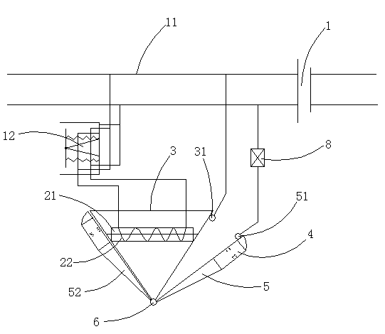
[0025] Such as figure 1 As shown, the magnetoelectric energy electric control switch includes a power supply 1 that provides direct current, wherein it also includes an iron core 22 with an electromagnetic coil 21 wound around its periphery in the axial direction, a fixing frame 3 for fixing the iron core 22 and a natural The pendulum 5 of the magnet 4, the electromagnetic coil 21 is electrically connected with the power supply 1 through the electric switch 12 through the wire 11, the pendulum 5 is provided with the first electric shock 51 electrically connected with the power supply 1, and the fixed frame 3 is provided with a power supply 1. The electrically connected second contactor 31, the pendulum frame 5 and the fixing frame 3 can make the first contactor 51 and the second contactor 31 come into contact with or separate from each other for movable cooperation.

[0026] In the embodiment, the swing frame 5 is a swing rod 52 located on both sides of the iron core 22. The s...

Embodiment 2

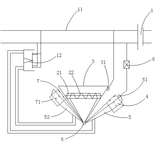
[0033] Such as figure 2 As shown, the structure of the magnetoelectric energy electric control switch in this embodiment is similar to that in Embodiment 1, the difference is that the electric switch 12 in this embodiment has no automatic reset function.

[0034] In the embodiment, a swing switch 7 is arranged between the swing frame 5 and the fixed frame 3, and an iron sheet 71 capable of attracting or separating from the natural magnet 4 is arranged on the swing switch 7; four groups of electric shocks are arranged on the swing switch 7, These four groups of electric shocks are respectively connected with four groups of wires, and the four groups of wires are respectively connected and matched with the electric switch 12 .

[0035] Working process: When the electrical equipment 8 is to be turned on, the electric switch 12 is closed to energize the electromagnetic coil 21, and the left end of the iron core 22 is an S pole, and the right end is an N pole. Due to the interacti...

Embodiment 3

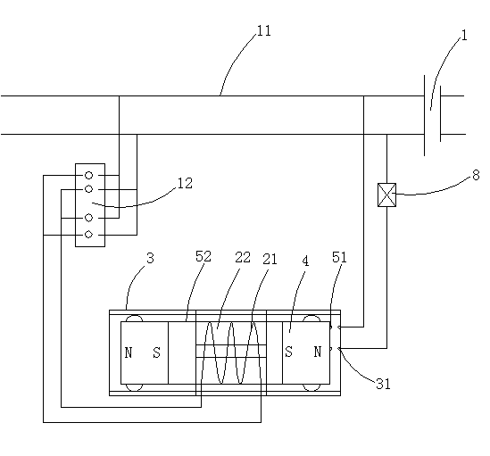
[0037] Such as image 3As shown, the magnetoelectric energy electric control switch in this embodiment is different from the above-mentioned embodiment in that the above-mentioned pendulum 5 is a rotating pendulum, while a translational pendulum is used in this embodiment;

[0038] In the embodiment, the pendulum frame 5 is a sliding frame 53 , and the two ends of the sliding frame 53 are respectively provided with natural magnets 4 , and the sliding frame 53 can slide left and right in the fixed frame 3 and cooperate with the fixed frame 3 movably.

[0039] In the embodiment, the sliding frame 53 is a rectangular frame structure, the natural magnets 4 are located at both ends of the rectangle, and the iron core 22 is located between the natural magnets 4 .

[0040] In the embodiment, the fixing frame 3 is a rectangular frame structure.

[0041] In the embodiment, the natural magnets 4 face each other with the same poles and are arranged at intervals. Here, the inner magnetic...


PUM


Abstract

The invention discloses a magneto-electric kinetic energy electric control switch which comprises a power supply which supplies direct currents. The magneto-electric kinetic energy electric control switch further comprises an iron core, a fixing frame and a swing frame, wherein an electro-magnetic coil is wound on the periphery of the iron core in the axial direction, the fixing frame is used for fixing the iron core, and a natural magnet is arranged on the swing frame. The electro-magnetic coil is electrically connected with the power supply through a wire after passing through an electric switch, a first contact which is electrically connected with the power supply is arranged on the swing frame, a second contact which is electrically connected with the power supply is arranged on the fixing frame, and the swing frame and the fixing frame can enable the first contact and the second contact to be matched movably in an electrical contacting mode or in a separating mode. The magneto-electric kinetic energy electric control switch is simple in structure, convenient to use, and wide in application. Besides, due to the fact that attraction force exists between the natural magnet and the iron core, after the electric switch is disconnected, the magneto-electric kinetic energy electric control switch has a self-locking function, and can keep a closing state or an opening state all the time. Therefore, not only is energy waste avoided, but also the phenomenon that the electro-magnetic coil is burned out due to long-time electrification is prevented from occurring. Therefore, reliability is improved and service life is prolonged.

Description

technical field [0001] The invention relates to an electromagnetic device, in particular to a magnetoelectric energy electric control switch. Background technique [0002] The emergence of electronically controlled switches enables people to operate electrical equipment remotely, which is not only convenient, but also allows people to work safely away from high-voltage power sources. At present, most of the electric control switches we use are electromagnetic relay switches, but this kind of switch has a disadvantage. When it turns on the power supply of the electrical equipment, it also needs to keep the power supply to its spiral coil, which not only wastes electric energy, but also And sometimes because the heat that the helical coil is energized for a long time is not easy to dissipate and burn out the helical coil, the whole switch is scrapped. [0003] Electromagnets have the advantages of simple structure and sensitive control, so electromagnets are widely used in ma...

Claims


Application Information

Patent Timeline
Patent Type & Authority Applications(China)
IPC IPC(8): H01H36/00
Inventor 赵德连
Owner 赵德连
Why Eureka
Try Eureka