
Micromachined monolithic 3-axis gyroscope with single drive

A gyroscope, three-axis acceleration technology, applied in gyroscope/steering sensing equipment, gyroscopic effect for speed measurement, microstructure devices composed of deformable elements, etc., can solve the problem of increasing the size of the three-axis accelerometer sensor, improving the cost, etc.

Active Publication Date: 2013-07-24
QST CORP
View PDF7 Cites 41 Cited by
  • Summary
  • Abstract
  • Description
  • Claims
  • Application Information

AI Technical Summary

Problems solved by technology

Adding multiple sensors or multiple masses to the mold increases the size and cost of the integrated triaxial accelerometer sensor

Method used


Image

  • Micromachined monolithic 3-axis gyroscope with single drive
  • Micromachined monolithic 3-axis gyroscope with single drive
  • Micromachined monolithic 3-axis gyroscope with single drive

Examples


Embodiment Construction

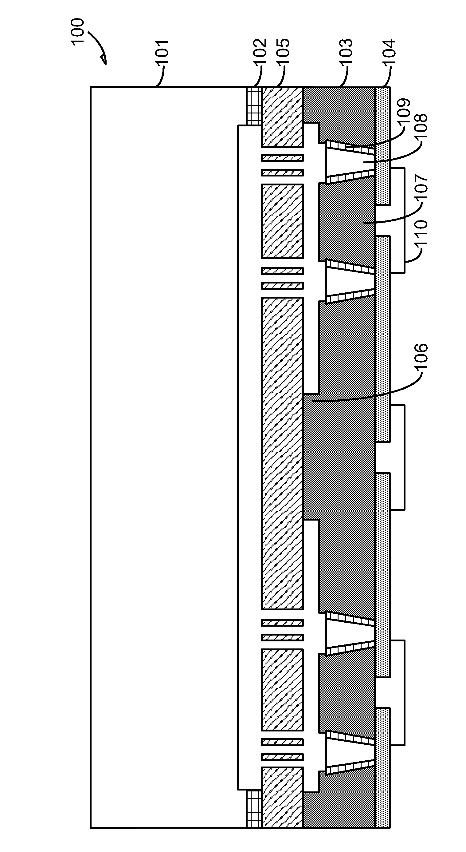
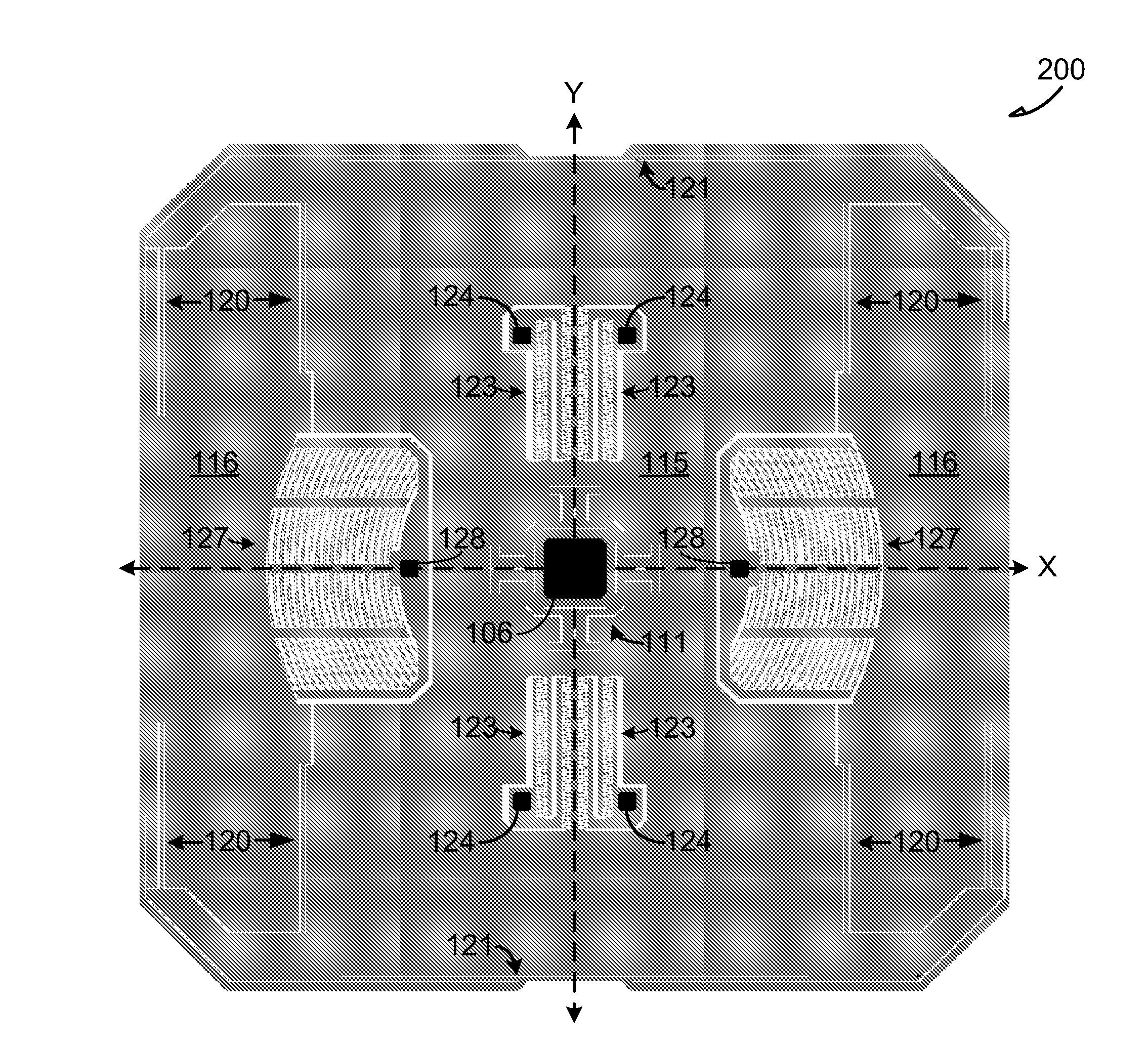
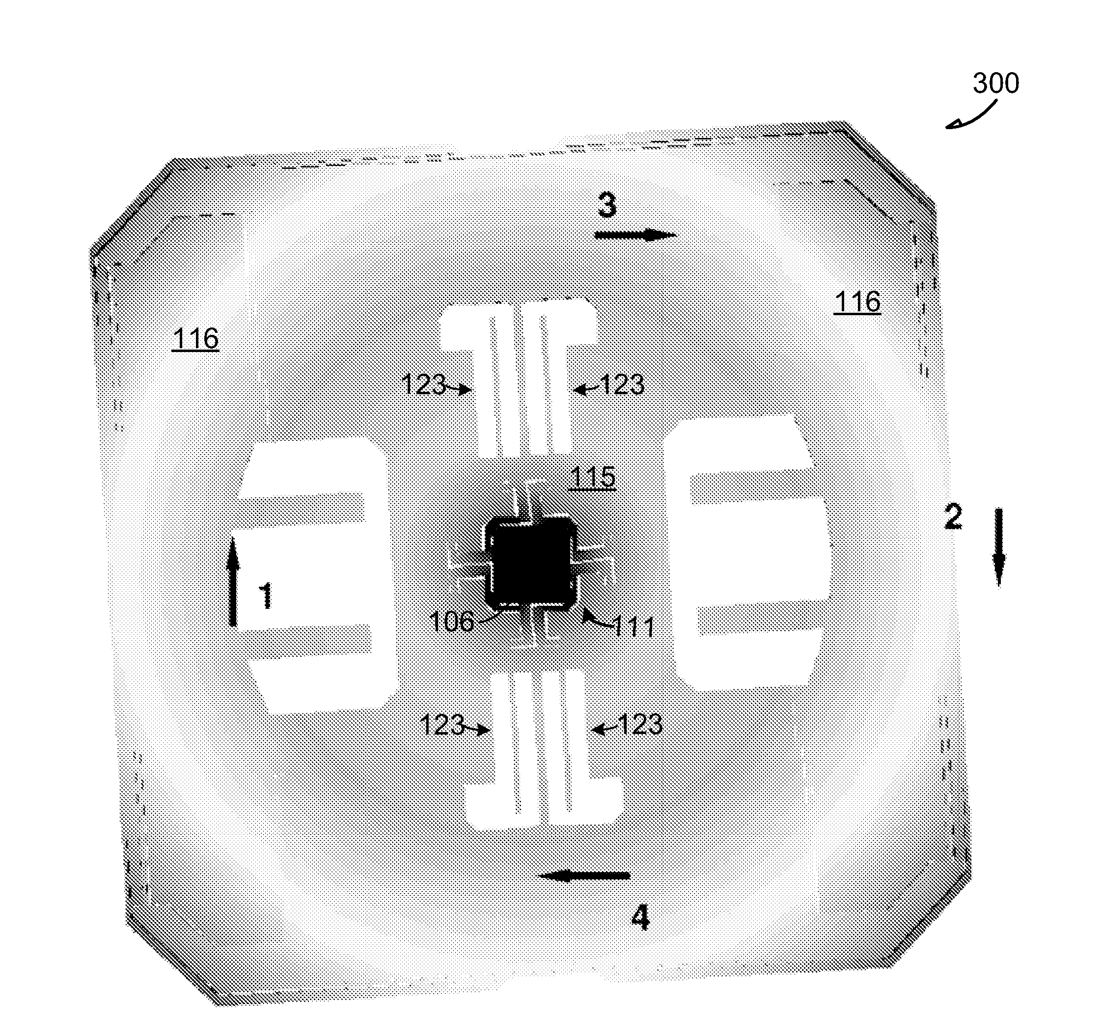
[0026] Among other things, the present inventors have recognized a micromechanical monolithic three-axis gyroscope configured to utilize a central A single fixed mass is used to detect angular rates around all three axes.

[0027] In one embodiment, the unique mass and compliant bearing structure disclosed in this application may allow triaxial angular rate detection with single drive mode vibration (requiring only one drive control loop for all axes). Thus, the complexity and cost of the control electronics in the three-axis gyroscope disclosed in this application is significantly reduced compared to existing multi-axis gyroscopes that use three separate drive loops.

[0028] Furthermore, the present inventors have recognized, among other things, a micromachined three-axis accelerometer configured to utilize a centrally fixed A single-mass to detect acceleration along all three axes.

[0029] In one embodiment, the unique mass and flexible bearing structure disclosed in thi...


PUM


Abstract

This document discusses, among other things, a cap wafer and a via wafer configured to encapsulate a single proof-mass 3-axis gyroscope formed in an x-y plane of a device layer. The single proof-mass 3-axis gyroscope can include a main proof-mass section suspended about a single, central anchor, the main proof-mass section including a radial portion extending outward towards an edge of the 3-axis gyroscope sensor, a central suspension system configured to suspend the 3-axis gyroscope from the single, central anchor, and a drive electrode including a moving portion and a stationary portion, the moving portion coupled to the radial portion, wherein the drive electrode and the central suspension system are configured to oscillate the 3-axis gyroscope about a z-axis normal to the x-y plane at a drive frequency.

Description

[0001] priority claim [0002] This application requires the U.S. Provisional Patent Application No. 61 / 384,245 filed on September 18, 2010 by the inventor Acar and entitled "Micromechanical Monolithic Three-Axis Gyroscope with Single Drive" (Attorney Case No. 2921.100PRV) and the U.S. Provisional Patent Application No. 61 / 384,246 filed by inventor Acar on September 18, 2010 and entitled "Micromechanical three-axis accelerometer with a single mass block" patent document (Proxy 2921.101PRV), each of which is incorporated herein by reference. [0003] In addition, the present application and the U.S. Patent Application No. 12 / 849,742 filed on August 3, 2010 by Acar et al. U.S. Patent Application No. 12 / 849,787 filed on August 3, 2009 and entitled "Micromechanical Devices and Methods of Manufacturing Same," each of which is incorporated herein by reference. technical field [0004] The present invention relates generally to inertial sensor devices, and more particularly to micr...

Claims


Application Information

Patent Timeline
IPC IPC(8): G01C19/5642B81B3/00G01C19/5755G01P15/18
CPCH01L29/84G01P15/125G01P15/18G01P2015/0848G01C19/5755B81B7/04B81B2201/0235B81B2201/0242B81B2203/051B81B2203/053B81B2203/055B81B2203/056B81B2203/058B81B2207/094
Inventor C·阿卡
Owner QST CORP
Learn More