Fault detection method, device and system for branch optical fiber

A technology of branching optical fiber and optical splitter, which is applied in the field of optical communication and can solve problems such as failure of OTDR testing at the ONU end

Inactive Publication Date: 2016-11-02
陆中尧
View PDF5 Cites 0 Cited by
  • Summary
  • Abstract
  • Description
  • Claims
  • Application Information

AI Technical Summary

Problems solved by technology

[0006] The embodiment of the present invention provides a fault detection method, device and system for a branch optical fiber, which can solve the problem that the OTDR test at the ONU end fails when the detected branch optical fiber is seriously faulty

Method used


Image

  • Fault detection method, device and system for branch optical fiber
  • Fault detection method, device and system for branch optical fiber
  • Fault detection method, device and system for branch optical fiber

Examples


Embodiment Construction

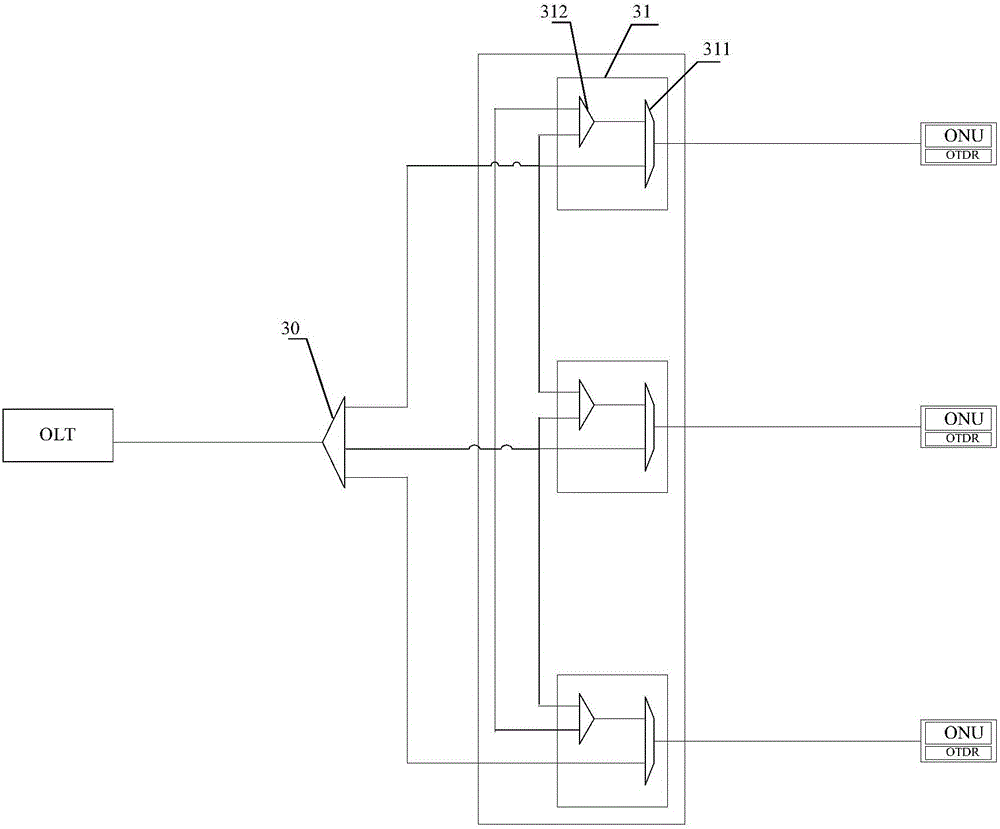
[0047] Embodiments of the present invention propose a fault detection method, device, and system for a branch fiber. By setting a passive branch looper between the optical splitter and multiple branch fibers, the passive branch looper can connect a branch fiber The test signal on the branch fiber is transmitted to another branch fiber, and the fault detection of the other branch fiber is performed, and the detection result on the other branch fiber can be sent to the OLT by the ONU on the aforementioned branch fiber, thus solving the problem of The problem of test failure caused by the serious fault of the branch fiber is solved, and the reliable detection of the fault of the branch fiber of the passive optical network is realized.

[0048] In order to enable those skilled in the art to better understand the technical solutions in the embodiments of the present invention, and to make the above-mentioned purposes, features and advantages of the embodiments of the present inventi...


PUM


Abstract

A branch optical fiber fault detection method, device and system; a passive branch loopback device comprises at least three branch units; the first branch unit receives via a first communication port a test signal transmitted by a first optical network unit when the second branch optical fiber fails, and transmits the test signal to the second branch unit via a loop; the second branch unit transmits the test signal to a second branch optical fiber via a first communication port thereof, detects the second branch optical fiber, and transmits the reflected signal of the test signal to the first optical network unit via the loop, so that the first optical network unit transmits to an optical line terminal a second branch optical fiber detection result obtained according to the reflected signal of the test signal. The passive branch loopback device solves the problem of a test failure due to a major fault of a to-be-tested branch optical fiber, and thus can reliably detect the fault of a branch optical fiber in a passive optical network.

Description

technical field [0001] The invention relates to the technical field of optical communication, in particular to a fault detection method, device and system for a branch optical fiber. Background technique [0002] With the development of broadband network technology, Passive Optical Network (PON) technology is currently one of the most widely used fiber-to-the-premises technologies. [0003] Passive optical network is a point-to-multipoint optical fiber access technology. Its structure is as follows: figure 1 As shown, including the optical line terminal (OLT, Optical Line Termination) located in the operator center, the passive optical distribution network (ODN, Optical Distribution Network) located in the field, and the optical network unit (ONU, OpticalNetwork Unit) located in the customer premises (Since the network positions and functions of ONU and ONT are basically the same, the ONU in this article also refers to Optical Network Termination (ONT, Optical Network Termi...

Claims


Application Information

Patent Timeline
Patent Type & Authority Patents(China)
IPC IPC(8): H04B10/075
CPCH04B10/071H04B10/272
Inventor 白茂森杨素林殷锦蓉王卫阳
Owner 陆中尧
Why Eureka
Try Eureka