Horizontally-arranged self-sealed stirring and transporting vehicle

A mixer truck, self-sealing technology, which is applied in concrete transportation, cement mixing device, clay preparation device, etc., can solve problems such as restricting the development of concrete mixer trucks, low carrying capacity, weak driving stability and safety, etc. problems, to achieve the effect of improving operability, large production workload, driving stability and safety

Inactive Publication Date: 2013-07-31
SHIYAN DAY SPECIAL PURPOSE VEHICLE TECH DEV
View PDF12 Cites 14 Cited by
  • Summary
  • Abstract
  • Description
  • Claims
  • Application Information

AI Technical Summary

Problems solved by technology

However, the use of traditional supporting wheels to support the weight and rotation of the tank body also fails to solve the effective fixation of the rear of the tank body, and the driving stability and safety of the vehicle are relatively weak; the rotary sealing mechanism of the mixing drum of the concrete mixer truck is affected by the characteristics of the transported materials. (such as sand, stones and other solid materials, etc.), it is difficult to achieve sealing, Yantai Shenglida Engineering Technology Co., Ltd. has added an automatic sand cleaning device (patent number: 201020502017) of the mixing drum rotary sealing mechanism (patent number: 201220471171) , cleaning devices, etc. to gradually improve
Since one end of the revolving airtight door must be fixed relative to the feed port and does not rotate, but the tank body must rotate, and displacement will occur due to bumps and swings, sand, stones and other solid objects will aff

Method used


Image

  • Horizontally-arranged self-sealed stirring and transporting vehicle
  • Horizontally-arranged self-sealed stirring and transporting vehicle
  • Horizontally-arranged self-sealed stirring and transporting vehicle

Examples


Embodiment Construction

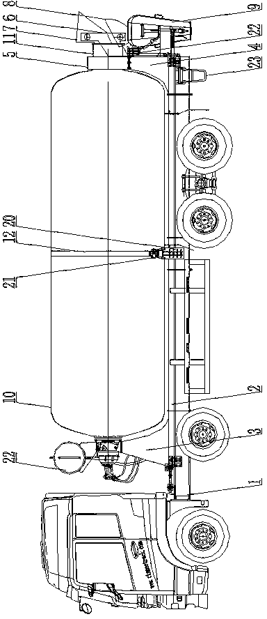
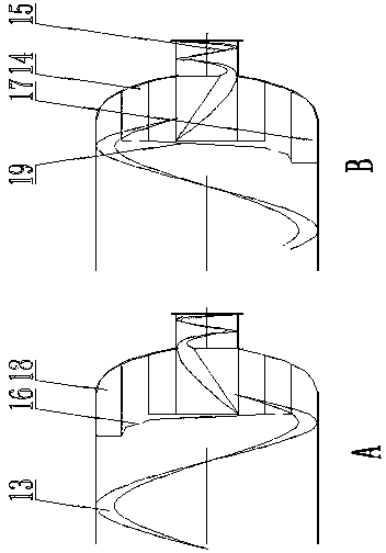
[0038] Such as figure 1 The shown agitator truck with tanks arranged horizontally includes a car chassis 1, a sub-frame 2 installed on the car chassis, a cleaning system 22, and a control system (not shown in the figure). The rear end is provided with a small step ladder 23 (convenient for operators to go up and down and maintain), and the tank body 10 is horizontally arranged on the subframe 2, and the front support 3 is fixed on the subframe 2, and the front support 3 is fixed with Hydraulic motor reducer assembly, the output axis of the hydraulic motor reducer assembly is set horizontally, the output end is fixedly connected with the tank body 10 through the flange, the middle part of the tank body 10 is provided with a ring raceway 12, and the two sides of the subframe are provided with There is a wing support frame 20, and the support roller 21 is fixed on the wing support frame 20. The rear part of the tank body 10 is provided with an inlet and outlet conduit 11, and th...


PUM


Abstract

The invention discloses a horizontally-arranged self-sealed stirring and transporting vehicle. A tank body is horizontally arranged on an auxiliary vehicle frame of an automobile chassis. The horizontally-arranged self-sealed stirring and transporting vehicle has the following innovations: a rotary disc bearing connecting flange I is arranged at the combined part of an inlet-outlet material guide pipe; a rotary disc bearing is connected between the rotary disc bearing connecting flange I and a rotary disc bearing foundation; the rotary disc bearing base is then fixed on a rear support; the rotary disc bearing firmly controls the tank body and rotates flexibly; materials are added in or output by utilizing the synchronous running and cooperation of three stirring cages; the liquid level of fluid is lifted by adopting a disc-type spiral lifting stirring cage, so that the loading liquid level exceeds the inlet-outlet material guide pipe and does not leak; the fluid does not overflow in ascending and bumping, and the disc-type spiral lifting stirring cage is insulated and sealed automatically; and the raceway nest support adopts a mode of supporting in the tank body, the tank body supporting intensity is improved, and the total height is not increased. The general design concept provided by the invention focuses on the driving stability, the safety performance, the market survival capability and loading and transportation capability of the stirring and transporting vehicle.

Description

technical field [0001] The invention relates to a new technology for automatically closing and horizontally arranging a stirring transport vehicle in a rotating state, in particular to a stirring transport vehicle in the field of engineering machinery. Background technique [0002] The concrete mixer truck is composed of a car chassis and a special device for concrete mixing. In the early stage, it was a proprietary technology in Germany and Japan, and they are all inclined rotating devices. Now the products of Chinese mixer truck manufacturers have their own technical characteristics, but they are all developed on the basis of the design of these two tanks. Its special mechanism mainly includes drive system, chassis support, tank body, feeding and discharging device, operating mechanism, cleaning system, etc. The working principle is to drive the variable pump of the hydraulic system by the power output of the car chassis through the power take-off device, convert the me...

Claims


Application Information

Patent Timeline
IPC IPC(8): B60P3/16B28C5/42
Inventor 郭红伟
Owner SHIYAN DAY SPECIAL PURPOSE VEHICLE TECH DEV
Why Eureka
Try Eureka