
Automobile brake signal light control system and control method

A technology of signal light control and automobile braking, applied in signal devices, optical signals, vehicle components, etc., can solve problems such as increasing the risk of rear-end collisions, reduce the risk of rear-end collisions, and improve active safety.

Active Publication Date: 2015-12-23
HANGZHOU BRANCH ZHEJIANG GEELY AUTOMOBILE RES INST +2
View PDF5 Cites 0 Cited by
  • Summary
  • Abstract
  • Description
  • Claims
  • Application Information

AI Technical Summary

Problems solved by technology

But this brings another problem. Because the brake pedal is not pressed, the brake light will not be lit. If the vehicle behind is close and does not slow down in time, the risk of rear-end collision will increase.

Method used


Image

  • Automobile brake signal light control system and control method

Examples


Embodiment Construction

[0023] In order to make the purpose, technical solutions and advantages of the embodiments of the present invention more clear, specific embodiments will be described in detail below with reference to the accompanying drawings.

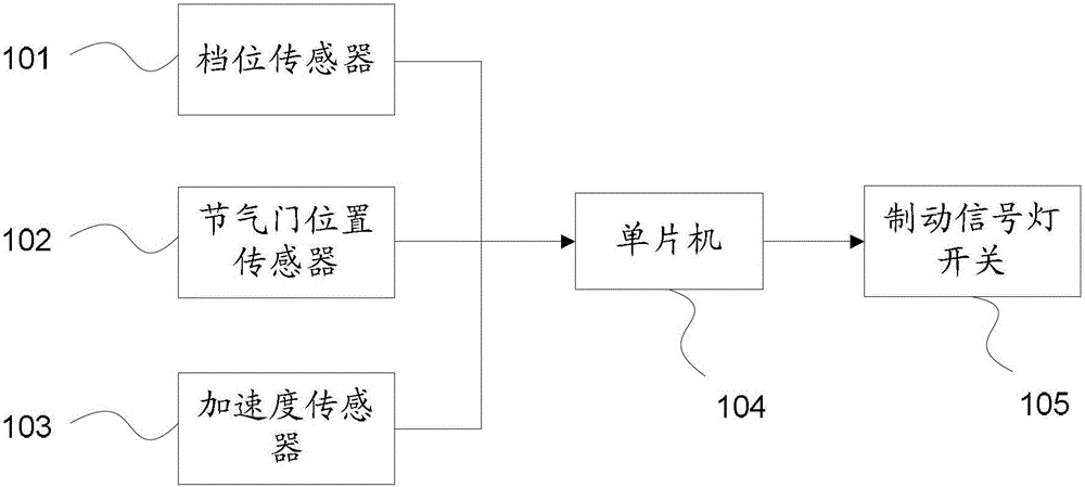
[0024] The automobile brake signal lamp control device of the present invention is used for automatically turning on the brake signal lamp under the condition that the automobile decelerates due to the idling operation of the engine, so as to remind the vehicles behind. Engine idling causes the car to decelerate. It can also be called engine braking, which refers to using the resistance generated when the engine is running to reduce the speed of the vehicle when the accelerator pedal is released. At this time, the engine not only cannot drive the vehicle forward, but consumes the kinetic energy of the vehicle, causing the engine to do negative work on the vehicle, thereby achieving the purpose of decelerating the vehicle. Here, it is not certain how m...


PUM


Abstract

The invention discloses a system and a method for controlling a brake signal lamp of an automobile. The system comprises a gear sensor, a throttle position sensor, an acceleration sensor and a singlechip, wherein the gear sensor is used for monitoring gear information in real time; the throttle position sensor is used for monitoring information about operation state of an engine; the acceleration sensor is used for monitoring information about deceleration value of the automobile in real time; and the singlechip is used for analyzing according to information monitored by the gear sensor, the throttle position sensor and the acceleration sensor; when the gear is shifted into a forward gear and the engine is in an idling operation state, and the deceleration value of the automobile reaches to a preset value, the brake signal lamp can be automatically opened, and another automobile in back of the automobile is timely prompted to carry out necessary deceleration and eluding. The system and the method can improve the active safety of the automobile and lower a risk of rear-end collision.

Description

technical field [0001] The invention relates to the field of automobile safety, in particular to an automobile brake signal light control system and a control method. Background technique [0002] In actual car driving, when encountering a red light intersection or when deceleration is required, the driver releases the accelerator pedal to allow the vehicle to decelerate using the traction resistance of the engine. oil state, saving fuel. But this brings another problem. Because the brake pedal is not pressed, the brake light will not be lit. If the vehicle behind is close and does not slow down in time, the risk of rear-end collision will increase. If the car is traveling at a high speed, the consequences will be even more unimaginable. Contents of the invention [0003] The object of the present invention is to provide a control system and a control method for brake signal lamps of an automobile aiming at the above-mentioned defects existing in the prior art. [0004]...

Claims


Application Information

Patent Timeline
Patent Type & Authority Patents(China)
IPC IPC(8): B60Q1/44
Inventor 康春风吴成明邹凌华戴礼强韩海强赵福全
Owner HANGZHOU BRANCH ZHEJIANG GEELY AUTOMOBILE RES INST
Learn More