
Main wirerope replacing tool of elevator

A wire rope and elevator technology, which is applied in the field of main wire rope replacement tools, can solve problems such as increasing the burden, and achieve the effects of reducing the burden, quickly changing operations, and high workability

Active Publication Date: 2013-07-31
HITACHI BUILDING SYST CO LTD
View PDF7 Cites 8 Cited by
  • Summary
  • Abstract
  • Description
  • Claims
  • Application Information

AI Technical Summary

Problems solved by technology

The main wire rope replacement tool 50 of the above-mentioned prior art increases the self-weight to apply the tension of the above-mentioned magnitude to the new main wire rope 1. Therefore, it is possible to increase the number of work required for the replacement of the main wire rope by the operator, including carrying work to the site and installation work. burden

Method used


Image

  • Main wirerope replacing tool of elevator
  • Main wirerope replacing tool of elevator
  • Main wirerope replacing tool of elevator

Examples


Embodiment Construction

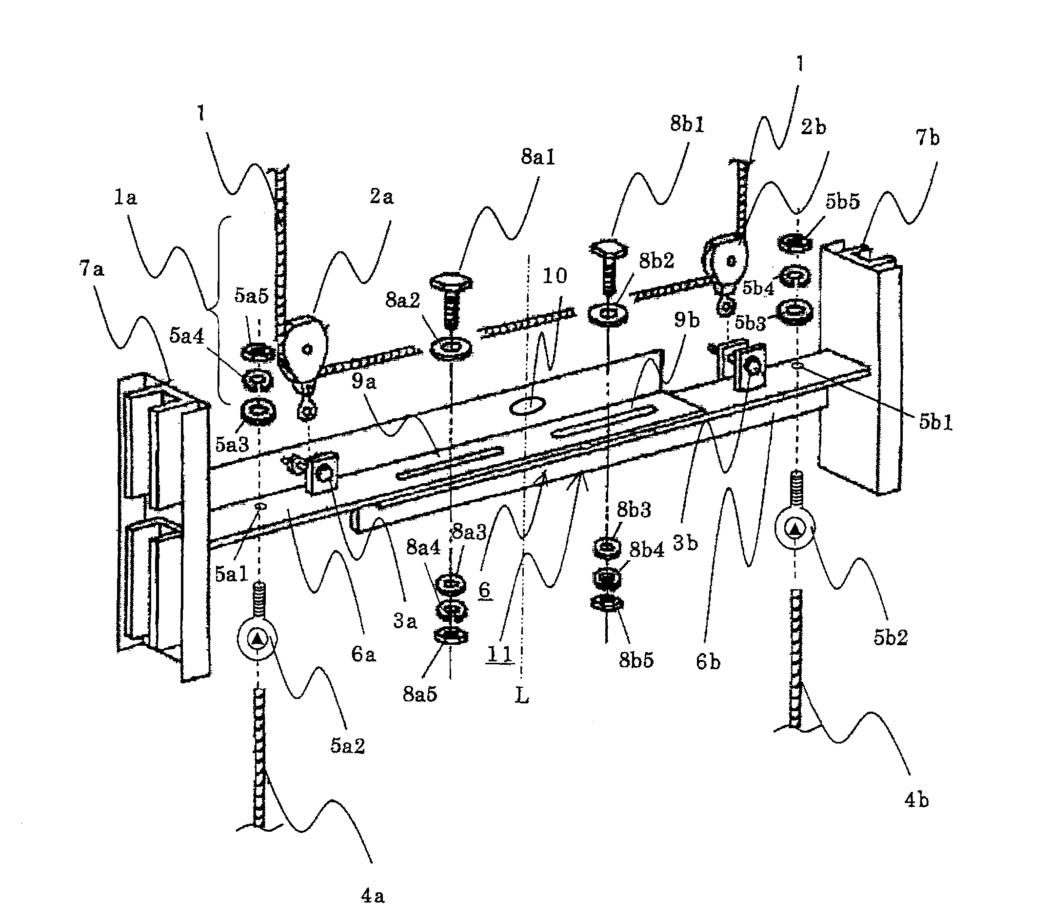
[0033] Next, the form of the main wire rope replacement tool used for the elevator which implements this invention is demonstrated based on drawing. In addition, the same code|symbol is attached|subjected to the part which overlaps with the description of the said prior art.

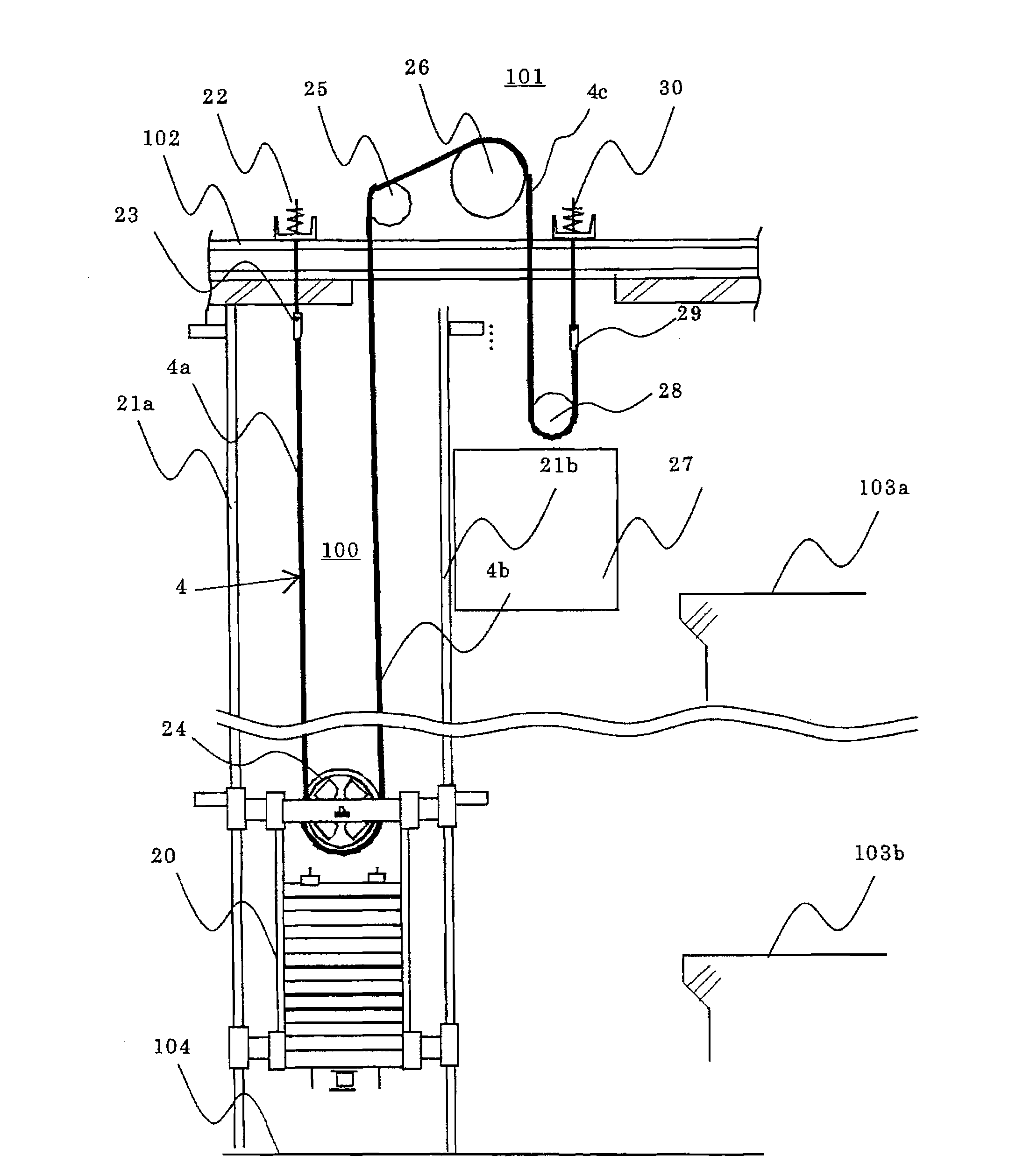
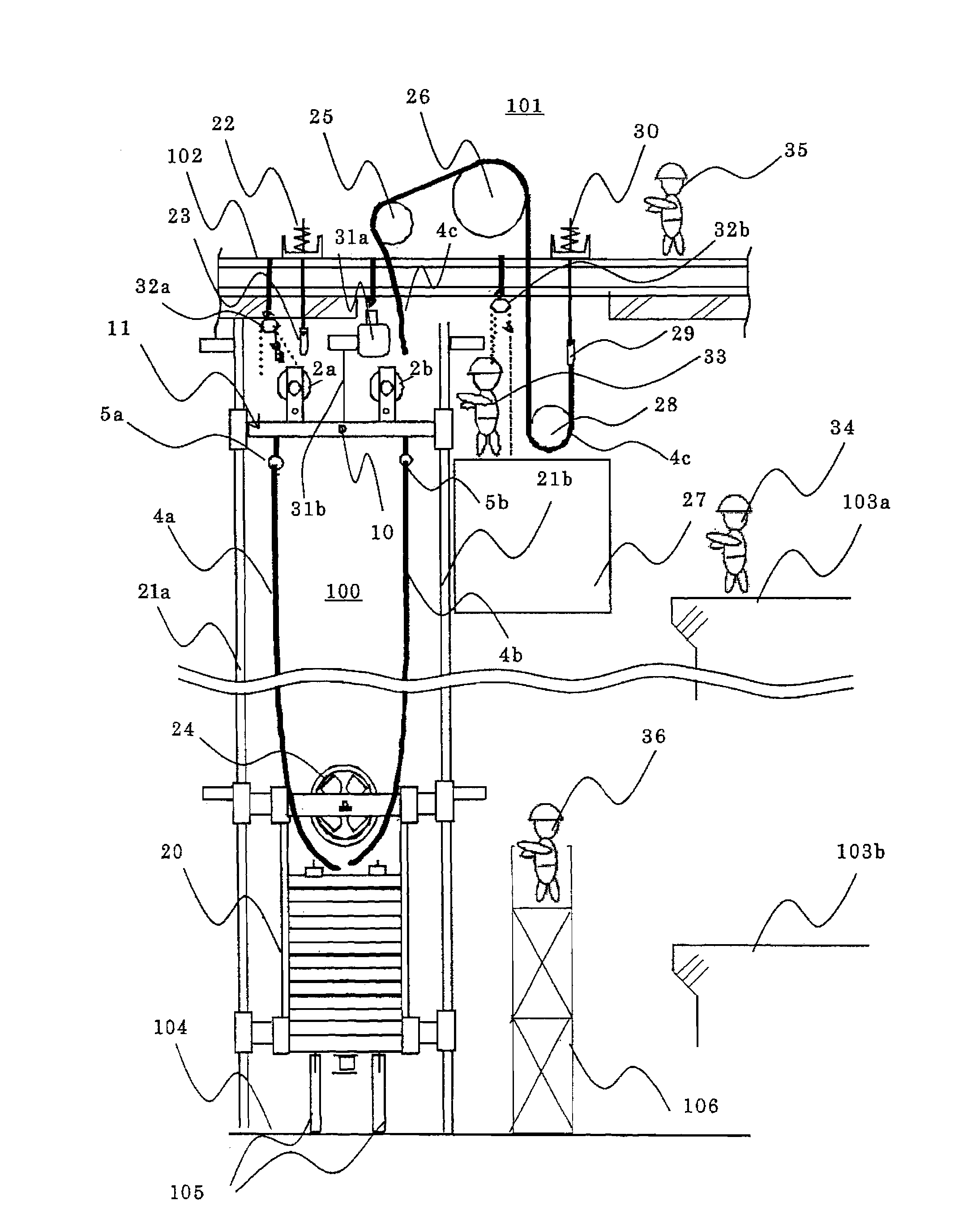
[0034] An embodiment of the main wire rope replacement tool of the elevator of the present invention is as follows: figure 2 The illustration shown is applicable to an elevator, which includes a car 27 arranged on the lifting path 100 and stopped at each floor, a counterweight 20 suspended by the car 27 and the main wire rope 4, and a pair of guide rails for guiding the counterweight 20 21a, 21b. In addition, in this embodiment, the elevator is constituted by a 2:1 pulling elevator, and the replacement work of the main wire rope 4 described later is mainly performed on the uppermost floor 103a and the lowermost floor 103b of each floor. In addition, a plurality of main steel wire ropes 4 are laid.

...


PUM


Abstract

The inveniton provides a main wirerope replacing tool of elevator, which can rapidly carry out the replacing work of main wirerope and reduct cost in the replacing work. The main wirerope replacing tool is applied to elevator and comprises a pair of guide rail (21a, 21b) for guiding a counterbalance (20) which hangs a cage (27) by the main wirerope, and the main wirerope replacing tool of elevator is used for replacing the used main wirerope (4) to a new main wirerope (1). The main wirerope replacing tool of elevator comprises a horizontal bar member (1) provided between the guide rails and arranged above the counterweight, a guiding member (7a, 7b) which is fixedly arranged at double ends of the horizontal bar and slidably installed on the guide rail; a stringing pulley (2a, 2b) which is installed on the horizontal bar memeber when winding the new wirerope; and a wirerope connecting mechanism (5a, 5b) which is provided on the horizontal bar member and connected to the used main wirerope (4a, 4b).

Description

technical field [0001] The present invention relates to a main wire rope replacement tool for an elevator for replacing an old main wire rope to be replaced with a new main wire rope for replacement. Background technique [0002] Figure 6 It is a figure explaining the operation|work of replacing a main wire rope using the main wire rope replacement tool of the conventional elevator. [0003] Generally, such as Figure 6 As shown, the elevator includes a lift path 100 , a machine room 101 provided on the upper portion of the lift path 100 , and a machine beam 102 provided on the machine room 101 . Furthermore, the elevator includes a car 27 provided on the lifting path 100 , a counterweight 20 that moves up and down relative to the car 27 , and a main wire rope (described later) that suspends the car 27 and the counterweight 20 in the lifting path 100 . , A pair of guide rails 21a, 21b for guiding the counterweight 20 . [0004] The machine room 101 includes a traction dev...

Claims


Application Information

Patent Timeline
IPC IPC(8): B66B7/00B66B19/02
Inventor 佐度昌仁
Owner HITACHI BUILDING SYST CO LTD
Learn More