Testing system for electronic delayers

A test system and delay device technology, applied in circuit breaker testing and other directions, can solve problems such as improper wiring, low work efficiency, complicated operation, etc., and achieve the effect of ensuring quality, speeding up development progress, and accurate detection.

Inactive Publication Date: 2013-07-31
HARBIN JIANCHENG GRP
View PDF5 Cites 2 Cited by
  • Summary
  • Abstract
  • Description
  • Claims
  • Application Information

AI Technical Summary

Problems solved by technology

The entire test process is complex in operation, low in efficiency, and heavy in workload. It requires high quality testers. Improper wiring often causes the delayer to burn out.

Method used


Image

  • Testing system for electronic delayers

Examples


Embodiment Construction

[0011] The present invention will be described in further detail below in conjunction with the accompanying drawings and embodiments.

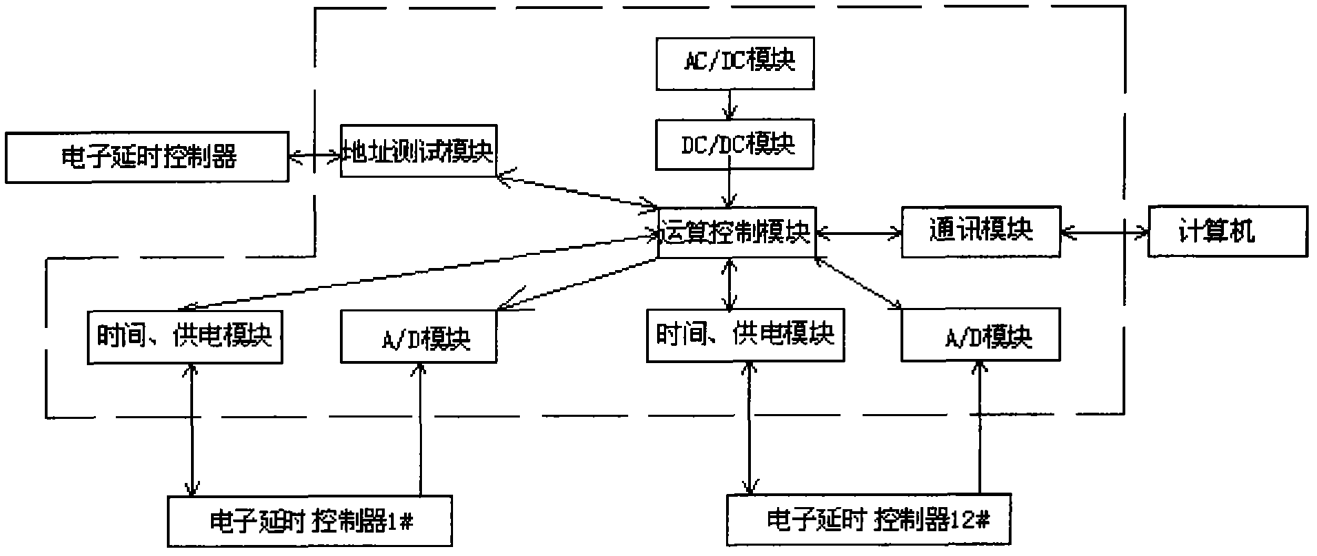
[0012] This embodiment is a specific electronic delayer test system realized according to the present invention, as attached figure 1 shown.

[0013] The electronic delayer test system shown in this embodiment includes an AC / DC module, a DC / DC module, an operation control module, an address test module, a communication module, a plurality of time power supply modules and a plurality of A / D modules, wherein each Each electronic delayer to be tested is respectively connected to an A / D module and a time power supply module through a test cable; the input end of the AC / DC module is connected to the AC power supply, and the output end is connected to the input end of the DC / DC module through the power line, and the DC The output end of the / DC module is connected to the operation control module through the power line; the operation control module ...


PUM


Abstract

The invention relates to a testing system for electronic delayers. The testing system comprises an AC / DC module, a DC / DC module, a computing control module, an address test module, a communication module, a plurality of time power supply modules and a plurality of A / D modules, wherein each to-be-tested electronic delayer is connected with an A / D module and a time power supply module respectively through testing cables; the input end of the AC / AD module is connected with an alternating current power supply; the output end of the AC / AD module is connected with the input end of the DC / DC module through a power line; the output end of the DC / DC module is connected with the computing control module through a power line; the computing control module is connected with the address test module, the communication module, each time power supply module and each A / D module through data lines; the communication module is connected to an industrial control computer through a data line and a communication interface; and the address test module is connected to one reference electronic delayer through a data line. The testing system can automatically finish testing the electronic delayers, the testing of the electronic delayers is more accurate, rapid, reliable and convenient, and the quality of the delayers is guaranteed.

Description

technical field [0001] The invention relates to a test system, in particular to a performance test system of an electronic delayer. Background technique [0002] The electronic delayer (referred to as the delayer) is a component that can be accurately delayed according to the set time, and is widely used in the field of intelligent control. As an important control part of the product, the delayer's action reliability is directly related to the use effect of the product. In order to ensure the quality of the electronic delayer in the scientific research and production stages, it is necessary to test its performance and set the delay time through testing equipment during the trial production and various tests of the electronic delayer. [0003] At this stage, the performance test of the delayer mainly relies on test equipment such as multimeters and oscilloscopes, and manually adjusts the power supply to supply power to the delayer. The entire testing process is complex in o...

Claims


Application Information

Patent Timeline
Patent Type & Authority Applications(China)
IPC IPC(8): G01R31/327
Inventor 徐振宇杨立峰董立刚冯喜郭晓双
Owner HARBIN JIANCHENG GRP
Why Eureka
Try Eureka