Rectangular rotary armature component for increasing rotatory inertia for magnetic latching relay
A magnetic latching relay, moment of inertia technology, applied in electromagnetic relays, electromagnetic relay details, relays, etc., can solve the problems of reducing the reliability of relays, and the relays cannot be disconnected normally, achieving novel design, increased inertia, and reasonable structure. Effect
- Summary
- Abstract
- Description
- Claims
- Application Information
AI Technical Summary
Problems solved by technology
Method used
Image
Examples
Embodiment 1
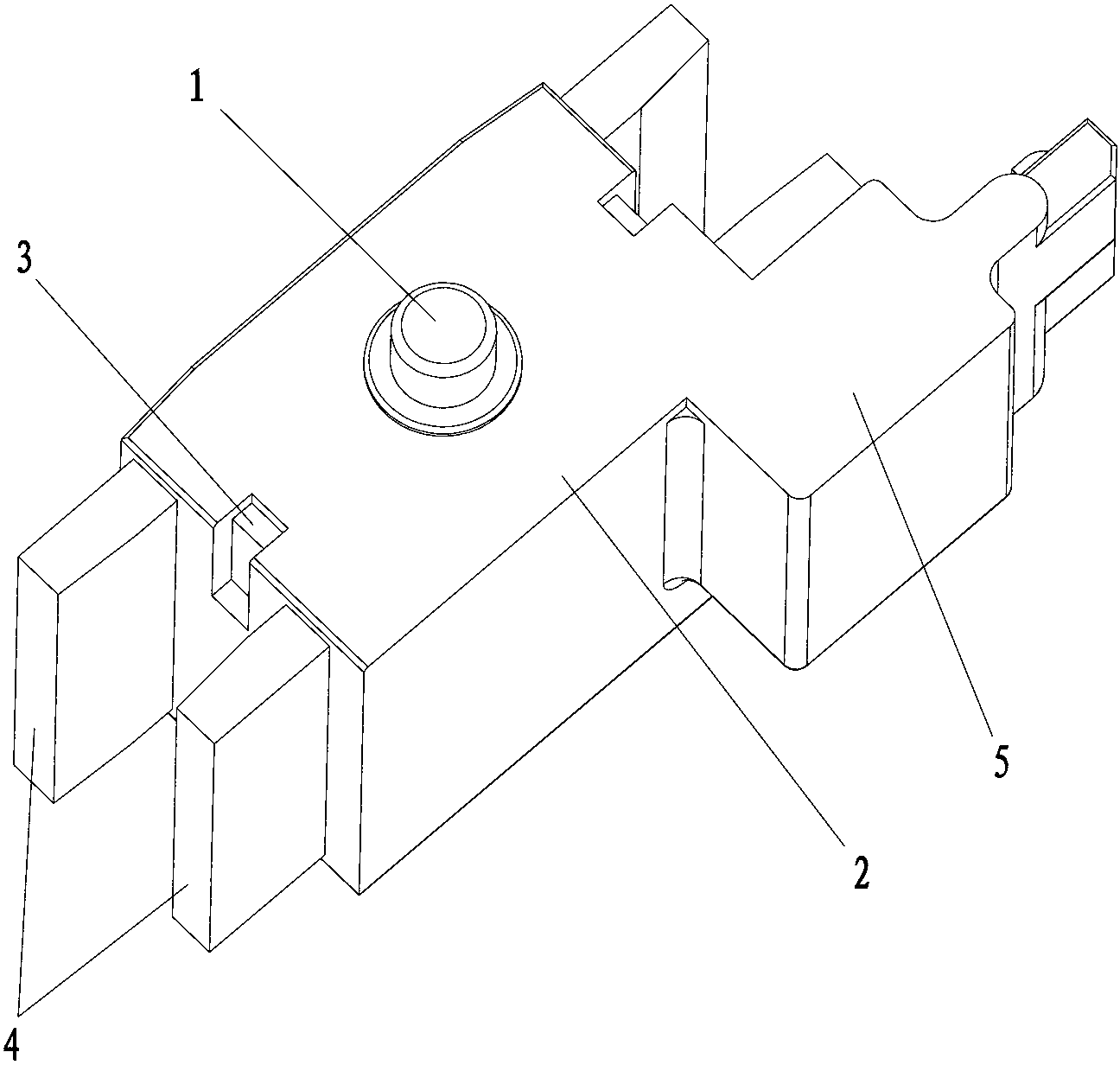
[0016] see figure 1 , the magnetic latching relay of the present invention increases the rotating moment of inertia type rotary armature assembly, which is I-shaped as a whole, including a housing 2 with a rotating shaft 1, a permanent magnet 3 and an armature 4 installed in the housing 2, and also includes The mass block 5 used to increase the rotational moment of inertia; the mass block 5 is far away from the rotating shaft 1 on the casing 2 , and is designed as an integrated structure with the casing 2 , and is arranged on the casing 2 .
Embodiment 2
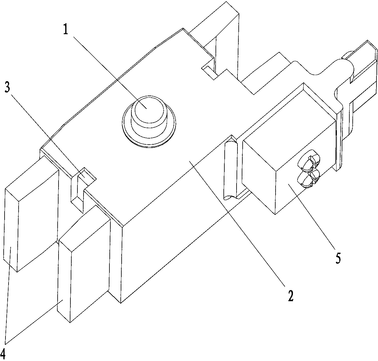
[0018] see figure 2 , the magnetic latching relay of the present invention increases the rotating moment of inertia type rotary armature assembly, which is I-shaped as a whole, including a housing 2 with a rotating shaft 1, a permanent magnet 3 and an armature 4 installed in the housing 2, and also includes The mass block 5 used to increase the rotational moment of inertia; the mass block 5 is far away from the rotating shaft 1 on the casing 2, and is designed as a split structure connected with the casing 2 by screws or rivets, and is arranged on the casing 2.
Embodiment 3
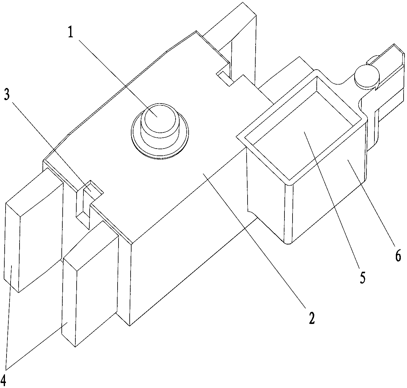
[0020] see image 3 , the magnetic latching relay of the present invention increases the rotating moment of inertia type rotary armature assembly, which is I-shaped as a whole, including a housing 2 with a rotating shaft 1, a permanent magnet 3 and an armature 4 installed in the housing 2, and also includes A mass block 5 for increasing the weight; the casing 2 is provided with an accommodating cavity 6 away from the rotating shaft 1 on the casing 2 , and the mass block 5 is placed in the accommodating cavity 6 of the casing 2 .
PUM
 Abstract
Description
Claims
Application Information
 - R&D
- Intellectual Property
- Life Sciences
- Materials
- Tech Scout
- Unparalleled Data Quality
- Higher Quality Content
- 60% Fewer Hallucinations
Browse by: Latest US Patents, China's latest patents, Technical Efficacy Thesaurus, Application Domain, Technology Topic, Popular Technical Reports.
© 2025 PatSnap. All rights reserved.Legal|Privacy policy|Modern Slavery Act Transparency Statement|Sitemap|About US| Contact US: help@patsnap.com


