
Positioning support leg for printed circuit board ink printing

A printed circuit board, ink printing technology, applied in printing, printing machines, rotary printing machines, etc., can solve the problems of affecting product quality, ink sticking, large contact area, etc., to avoid ink sticking and reduce contact area. Effect

Inactive Publication Date: 2013-08-07
KUNSHAN HANHUI ELECTRONICS TECH CO LTD
View PDF8 Cites 0 Cited by
  • Summary
  • Abstract
  • Description
  • Claims
  • Application Information

AI Technical Summary

Problems solved by technology

Since the above-mentioned traditional solder resist printing ink process is to print and bake the two sides of the printed circuit board separately, this will cause inconsistencies such as color difference in the ink layers on both sides of the printed circuit board.
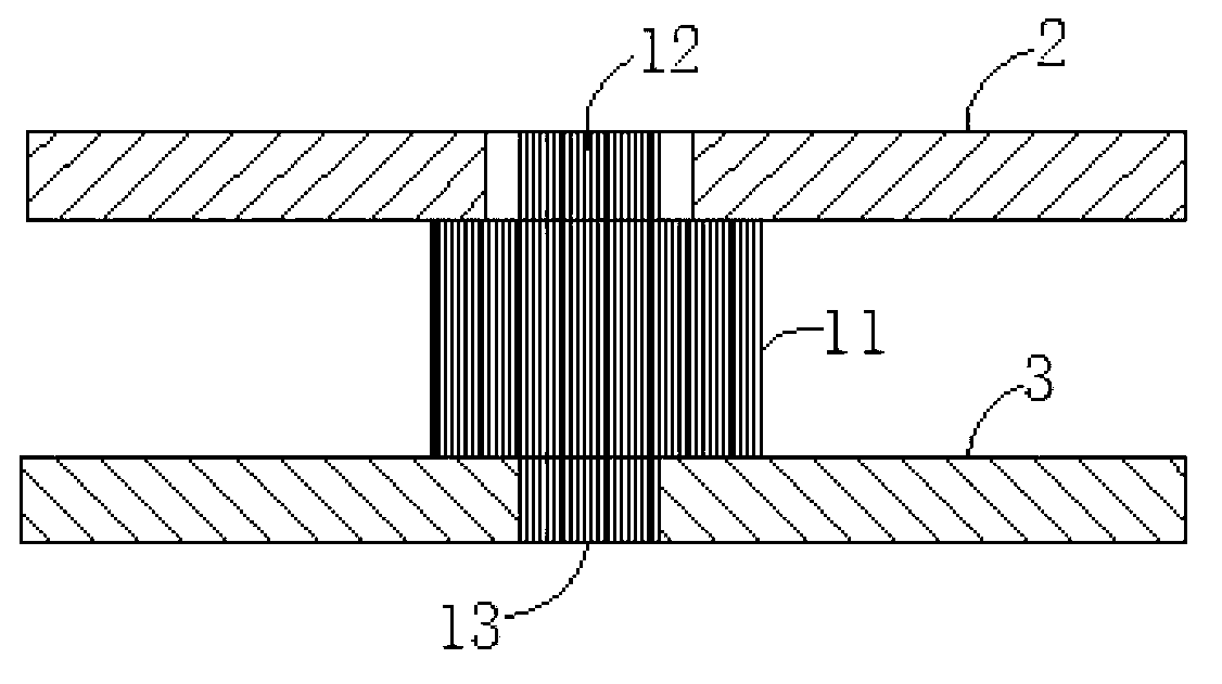
Therefore, some people in the industry have improved the process of solder resist printing ink. After printing ink on one side of the printed circuit board, the board is turned over to print ink on the other side of the printed circuit board, and then the printed circuit board is put into the oven for printing. The two sides of the circuit board are baked and cured at the same time. Although this improved process solves the above-mentioned inconsistency between the two sides, it has the following defects: because the ink on one side of the printed circuit board is not dried after printing, it enters the ink printing on the other side. In this way, the side that has printed the ink but has not been baked and cured is in contact with the upper surface of the elevating stand, and because the upper surface of the supporting column of the elevating stand is flat, the contact area with the printed circuit board is large, and it is easy to make the ink Sticky, which affects the quality of the product

Method used


Image

  • Positioning support leg for printed circuit board ink printing
  • Positioning support leg for printed circuit board ink printing

Examples


Embodiment

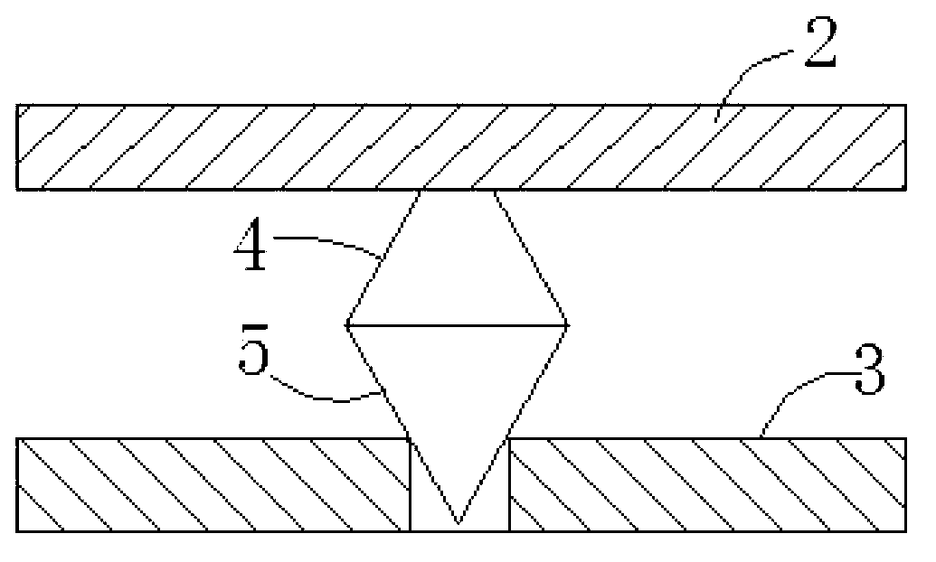
[0009] Embodiment: A positioning support for printed circuit board ink printing, consisting of an upper support 4 and a lower positioning pin 5, the upper support is in the shape of a truncated cone, the lower positioning pin is conical, and the upper plane of the upper support is Smaller than the lower plane of the upper support, the cone point of the lower positioning pin faces downward, and the lower positioning pin extends downward from the lower plane of the upper support, and the cone point of the lower positioning pin 5 Smaller than the positioning hole of the backing plate 3 on the machine platform and the upper end is larger than the positioning hole of the backing plate on the machine platform, and the lower positioning pin is inserted in the positioning hole of the backing plate, the upper plane of the upper support 4 supports the A printed circuit board.


PUM


Abstract

The invention discloses a positioning support leg for printed circuit board ink printing. The positioning support leg is formed by an upper support and a lower positioning pin, wherein the upper support is truncated-cone-shaped, and the lower positioning pin is conical. The upper plane of the upper support is smaller than the lower plane of the upper support. The conical tip of the lower positioning pin faces downwards, the lower positioning pin is formed by downwards integrally extending from the lower plane of the upper support and is inserted into a positioning hole of a base plate, and the upper plane of the upper support supports a printed circuit board. The positioning support leg achieves elevating and positioning of the printed circuit board, reduces the contact area of the support leg and the printed circuit board due to the fact that the area of the upper plane of the upper support is small, and can avoid ink sticking.

Description

technical field [0001] The invention belongs to a positioning device used in the production process of a printed circuit board, in particular to a support foot used for elevating and positioning a printed circuit board when solder resist printing ink is used. Background technique [0002] Printed circuit boards (PCBs) generally print ink on one side of the printed circuit board first when printing ink on solder resist, bake and cure the ink on this side, turn the printed circuit board over, and then print ink on the other side of the printed circuit board, and then Bake and cure the ink on the other side, such as figure 1 As shown, during the solder resist printing ink, the printed circuit board 2 is elevated and positioned above the backing plate 3 on the machine table through the elevating stand (elevating PIN). The traditional elevating stand generally has a supporting column 11 and an upper, Lower positioning feet 12, 13, the support cylinder is used for elevating and s...

Claims


Application Information

Patent Timeline
IPC IPC(8): B41F15/18
Inventor 薛东妹
Owner KUNSHAN HANHUI ELECTRONICS TECH CO LTD
Learn More