
Automobile frame for automobile and automobile with same

A frame and vehicle technology, which is applied in the field of non-load-bearing frames and vehicles with the frame, can solve the problems of compressed fuel tank installation space, fuel tank deformation, and poor practicability, and achieve improved safety, lightweight design, and good performance. The effect of collision energy

Active Publication Date: 2013-08-07
GREAT WALL MOTOR CO LTD
View PDF6 Cites 67 Cited by
  • Summary
  • Abstract
  • Description
  • Claims
  • Application Information

AI Technical Summary

Problems solved by technology

[0002] A traditional non-load-bearing frame is generally formed by two side beams and a plurality of beams connected between the two side beams, wherein the engine, transmission, vibration damping components, etc. are all arranged on the frame, in order to protect these components As well as the safety of the cockpit, the front and rear anti-collision beams are generally installed on the front and rear sections of the frame longitudinal beams. However, when the energy of the frontal collision or rear collision is large in this traditional setting method, the front and rear anti-collision beams cannot be well absorbed. Collision energy, that is, most of the collision energy will still be transmitted to the center of the frame, which is easy to damage the engine, transmission and vibration damping components. In severe cases, it may cause severe deformation of the cockpit, threatening the personal safety of the driver and passengers in the cockpit. low safety factor
[0003] Moreover, generally speaking, the fuel tank is generally arranged at the rear of the middle of the non-load-bearing frame. During the rear collision, because the rear anti-collision beam cannot absorb the collision energy well, the installation space of the fuel tank may be severely compressed. , resulting in deformation of the fuel tank, oil leakage or even explosion. At the same time, the frame with the rear anti-collision beam also increases the overall cost of the frame, which is less practical

Method used


Image

  • Automobile frame for automobile and automobile with same
  • Automobile frame for automobile and automobile with same
  • Automobile frame for automobile and automobile with same

Examples


Embodiment Construction

[0032] Embodiments of the present invention are described in detail below, examples of which are shown in the drawings, wherein the same or similar reference numerals designate the same or similar elements or elements having the same or similar functions throughout. The embodiments described below by referring to the figures are exemplary and are intended to explain the present invention and should not be construed as limiting the present invention.

[0033] In describing the present invention, it should be understood that the terms "center", "longitudinal", "transverse", "length", "width", "thickness", "upper", "lower", "front", " Orientation or position indicated by "back", "left", "right", "vertical", "horizontal", "top", "bottom", "inner", "outer", "clockwise", "counterclockwise", etc. The relationship is based on the orientation or positional relationship shown in the drawings, and is only for the convenience of describing the present invention and simplifying the descrip...


PUM


Abstract

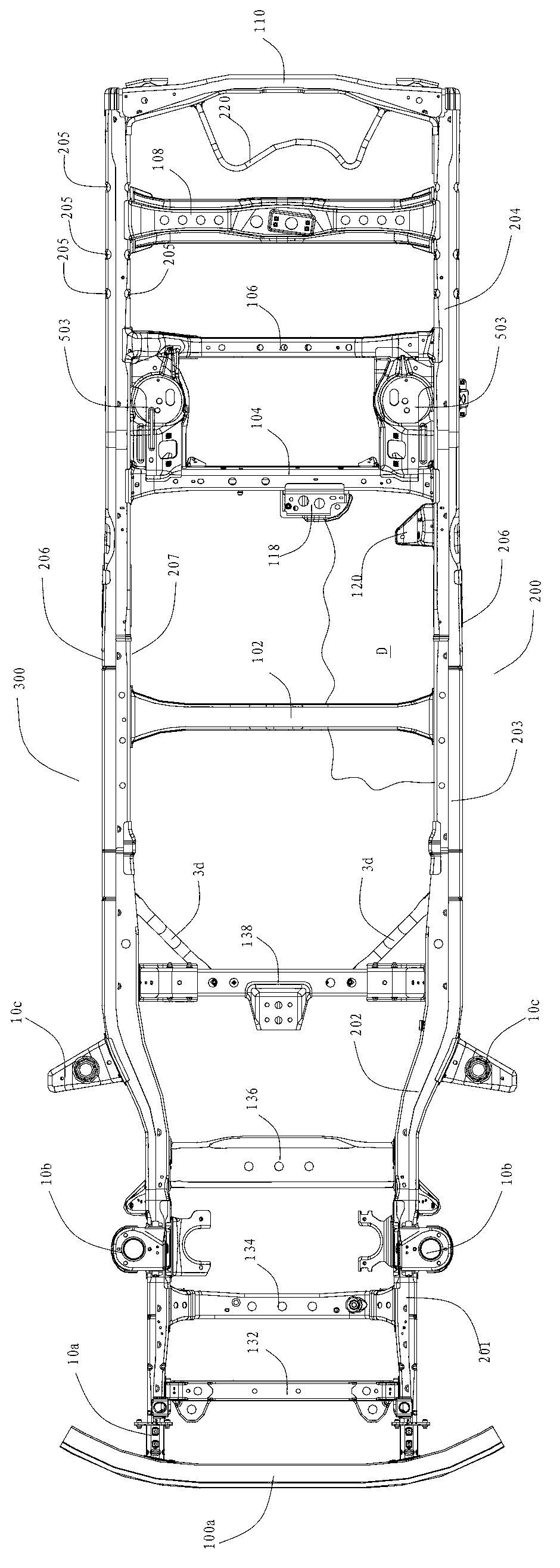
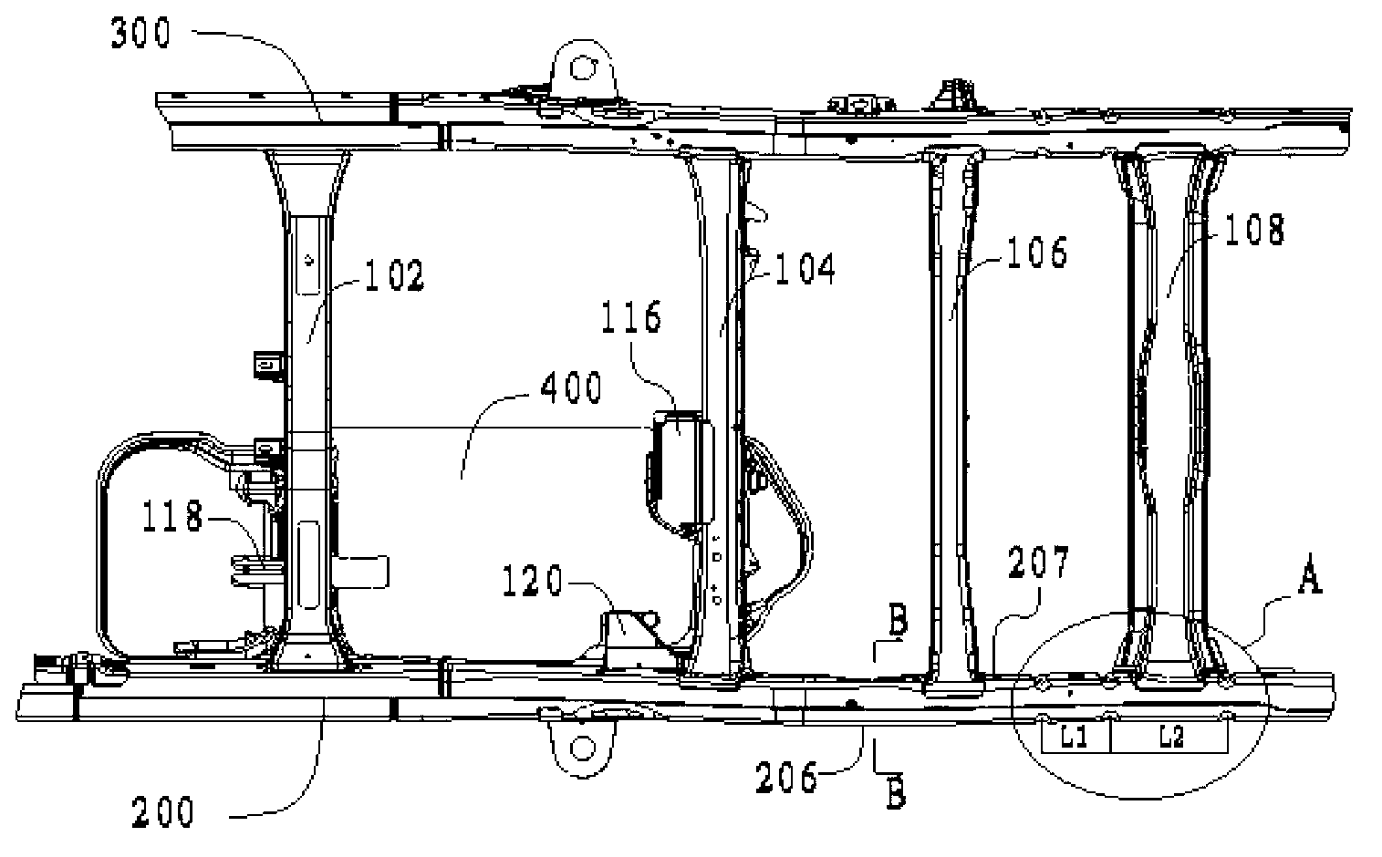
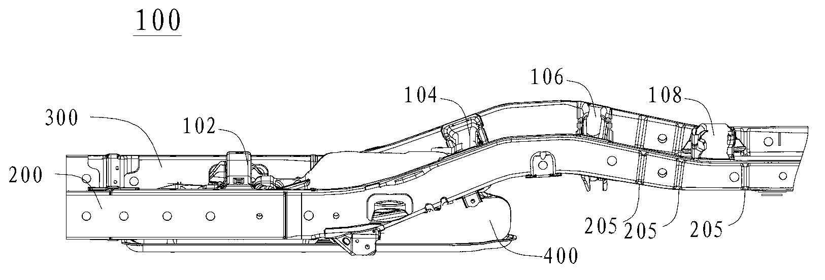
The invention discloses an automobile frame and an automobile. The automobile frame comprises two longitudinal beams, a plurality of beams, a front anti-collision beam and energy absorption boxes. The two longitudinal beams are mutually separated, each longitudinal beam is provided with a front section, a connection section, a middle section and a back section, wherein an energy absorption structure is arranged on the back section. The plurality of beams are arranged between the two longitudinal beams. The front anti-collision beam is arranged at the front ends of the two longitudinal beams and comprises a first upper plate, a first middle plate, a first lower plate, a first lateral plate and a second lateral plate. The first lateral plate and the second lateral plate are connected between the front ends of the back ends of the first upper plate and the first lower plate respectively, the first middle plate is arranged between the first upper plate and the first lower plate and connected with the first lateral plate and the second lateral plate respectively, and the thicknesses of the first middle plate, the first upper plate and the first lower plate are approximately identical. The two energy absorption boxes are arranged between the front anti-collision beam and the two longitudinal beams respectively. The automobile frame has the improved front collision and back collision resistance, improves collision resistance, protects an oil tank and simultaneously reduces deformation of a cab.

Description

technical field [0001] The invention relates to the technical field of automobile construction, in particular to a non-load-bearing frame for a vehicle and a vehicle with the frame. Background technique [0002] A traditional non-load-bearing frame is generally formed by two side beams and a plurality of beams connected between the two side beams, wherein the engine, transmission, vibration damping components, etc. are all arranged on the frame, in order to protect these components As well as the safety of the cockpit, the front and rear anti-collision beams are generally installed on the front and rear sections of the frame longitudinal beams. However, when the energy of the frontal collision or rear collision is large in this traditional setting method, the front and rear anti-collision beams cannot be well absorbed. Collision energy, that is, most of the collision energy will still be transmitted to the center of the frame, which is easy to damage the engine, transmission...

Claims


Application Information

Patent Timeline
Patent Type & Authority Applications(China)
IPC IPC(8): B62D21/15B60R19/04
Inventor 黄勇徐波王志明李勇君宋红双张露张清芳曹大为李海涛
Owner GREAT WALL MOTOR CO LTD
Learn More