
Vibration assisted well drilling simulation device

A simulation device and drilling technology, applied in drilling equipment, earthwork drilling, drilling equipment and methods, etc., can solve the problems of slow drilling speed and low efficiency, and achieve the effect of speeding up drilling speed

Inactive Publication Date: 2013-08-07
YANGZHOU UNIV
View PDF8 Cites 14 Cited by
  • Summary
  • Abstract
  • Description
  • Claims
  • Application Information

AI Technical Summary

Problems solved by technology

With the device of this structure, the drilling speed is slow and the efficiency is low

Method used


Image

  • Vibration assisted well drilling simulation device
  • Vibration assisted well drilling simulation device
  • Vibration assisted well drilling simulation device

Examples


Embodiment Construction

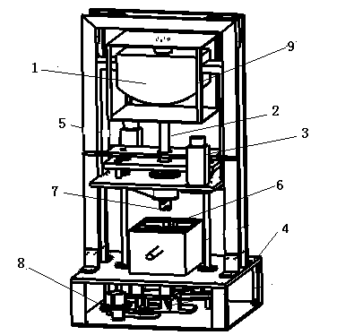
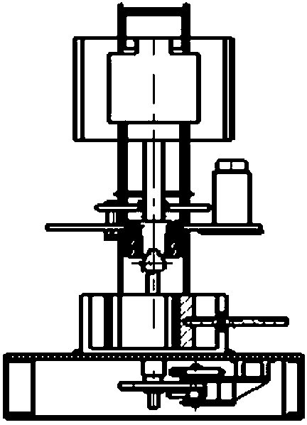
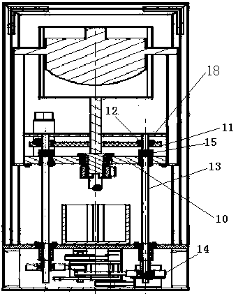
[0031] Such as figure 1 , 2 , 3, the vibration-assisted drilling simulation device includes a frame 4, a servo motor 8, a clamping device 6, two screw nut mechanisms, two jacks 16, a drill bit 17, a load plate 10, a load plate 11, and a rotating motor 3. Exciting table 1, square frame 9 and shock rod 2. Columns 5 are installed at both ends of the frame 4 .

[0032] A clamping device 6 is installed on the base plate of the frame 4, a servo motor 8 is installed at the bottom of the base plate, and gears are installed on the motor shaft of the servo motor 8. Lead screw nut mechanism is symmetrically arranged on both sides of clamping device 6, and the lower end of lead screw 13 passes through the frame bottom plate and is connected to the gear on the servo motor 8 motor shaft by the gear on the lead screw and the synchronous toothed belt 14, the lead screw The upper end of 14 passes through the bearing plate 10 and the loading plate 11 successively, and the nut 12 is fixed on ...


PUM


Abstract

A vibration assisted well drilling simulation device comprises a frame, a column, a servo motor, a rock clamping deivce, lead screw and nut mechanisms, a drill bit, a bearing plate, a loading plate, a rotating motor, a vibration excitation table, a four-side square framework and an impact rod. The clamping deivce is arranged on a base plate of the frame, and the servo motor is arranged at the bottom of the base plate. The lead screw and nut mechanisms are symmetrically arranged on two sides of the clamping deivce, the lower ends of lead screws penetrate through the base plate of the frame and are connected with gears disposed on a motor shaft of the servo motor through gears disposed on the lead screws and synchronous cog belts, the upper ends of the lead screws sequentially penetrate through the bearing plate and the loading plate, and nuts are fixed on the loading plate. The drill bit is arranged at the bottom of the bearing plate disposed above the rock clamping device, and the rotating motor drives and is connected with the drill bit. The vibration excitation table moves vertically through matching of an outer side guide rail and an inner side guide rail. The four-side square framework is vertical and surrounds the vibration excitation table, and the impact rod is vertically arranged at the bottom of the four-side square framework. The vibration assisted well drilling simulation device is ingenious in concept, simple in structure and high in well drilling efficiency, and greatly improves well drilling speed.

Description

technical field [0001] The invention relates to a vibration-assisted drilling simulation device, which is suitable for studying the change of rock characteristics and the influence of vibration on the rock-breaking ability of a drill bit under the conditions of low-frequency large-amplitude and high-frequency small-amplitude respectively, and belongs to the technical field of resonance drilling rock-breaking. Background technique [0002] Vibration phenomena widely exist in various material media, such as metallic materials (steel, aluminum, various non-ferrous metals) and non-metallic materials (rocks, ceramics, glass, cement) and so on. The rock vibration excitation simulation test system is a test system including vibration excitation simulation and test analysis. The system can be used to analyze the vibration characteristics of various materials. [0003] Its main functions mainly include two aspects: one is to make the rock generate various excitation signals, such as...

Claims


Application Information

Patent Timeline
IPC IPC(8): E21B7/00
Inventor 王昌龙张庆田竺志大赵山华边义祥戴隆超沈辉刘建杜建周
Owner YANGZHOU UNIV
Learn More