Multiple-working-face parallel working process for shaft ground pre-grouting

A multi-face, parallel operation technology, applied in wellbore/well components, earthwork drilling, sealing/isolation, etc., can solve problems such as long well construction period, backward directional technology, single means, etc., to ensure quality, The effect of shortening the well construction period and speeding up the construction speed

Inactive Publication Date: 2013-08-07
张新立
View PDF6 Cites 9 Cited by
  • Summary
  • Abstract
  • Description
  • Claims
  • Application Information

AI Technical Summary

Problems solved by technology

The traditional solution of straight hole grouting uses a water source drilling rig to drill the grouting hole, which occupies the position of the wellhead. Subsequent construction such as freezing or sinking can only be carried out after the grouting is completed. Parallel operations such as injection, freezing, and drilling cannot be performed. Relatively long, generally 800 to 1,000 meters of wellbore, the grouting cycle is about one and a half years
S-hole directional technology is relatively backward. The difficulty of S-hole construction technology lies in the inaccuracy of directional trajectory. This has a lot to do with the domestic self-developed directional technology adopted by the current geology and mining industry. The directional technology of my country's geology and mining industry is relatively backward. relatively simple means
Often because the directional trajectory control is not up to standard, the grouting diffusion range cannot be crossed, the grouting effect is not ideal, and there is a considerable risk. At present, the failure of some engineering examples has caused many construction units to resist when choosing a construction plan mood

Method used


Image

  • Multiple-working-face parallel working process for shaft ground pre-grouting
  • Multiple-working-face parallel working process for shaft ground pre-grouting
  • Multiple-working-face parallel working process for shaft ground pre-grouting

Examples


Embodiment

[0019] 1. Establish a grouting station

[0020] 2. The drilling rig starts drilling operations

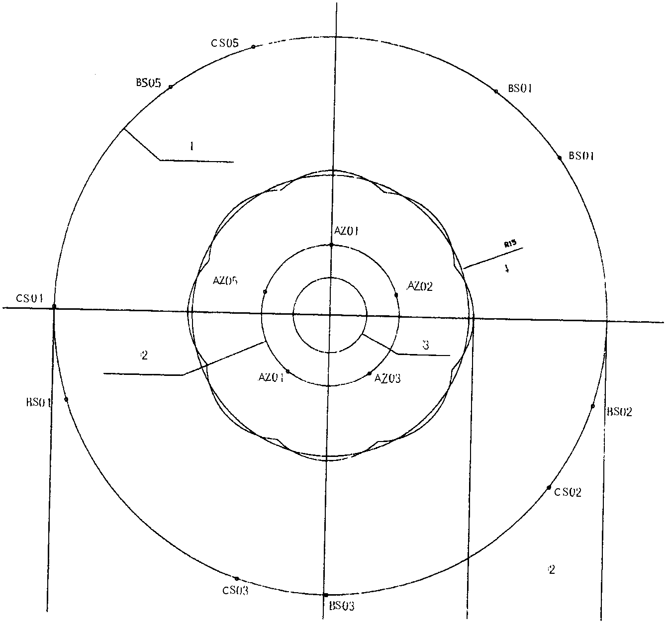
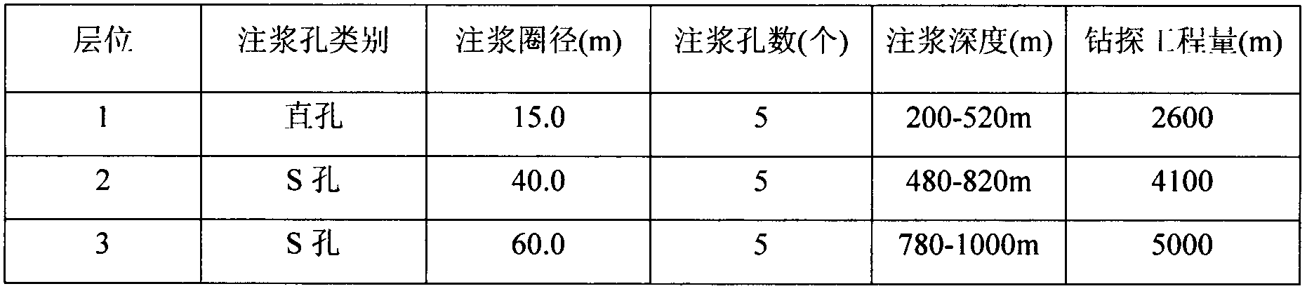
[0021] (1) Straight holes are arranged at the wellbore position. The initial depth of the grouting face of the first layer is 200m, and the final depth is 520m (40m with the grouting section of the second layer).

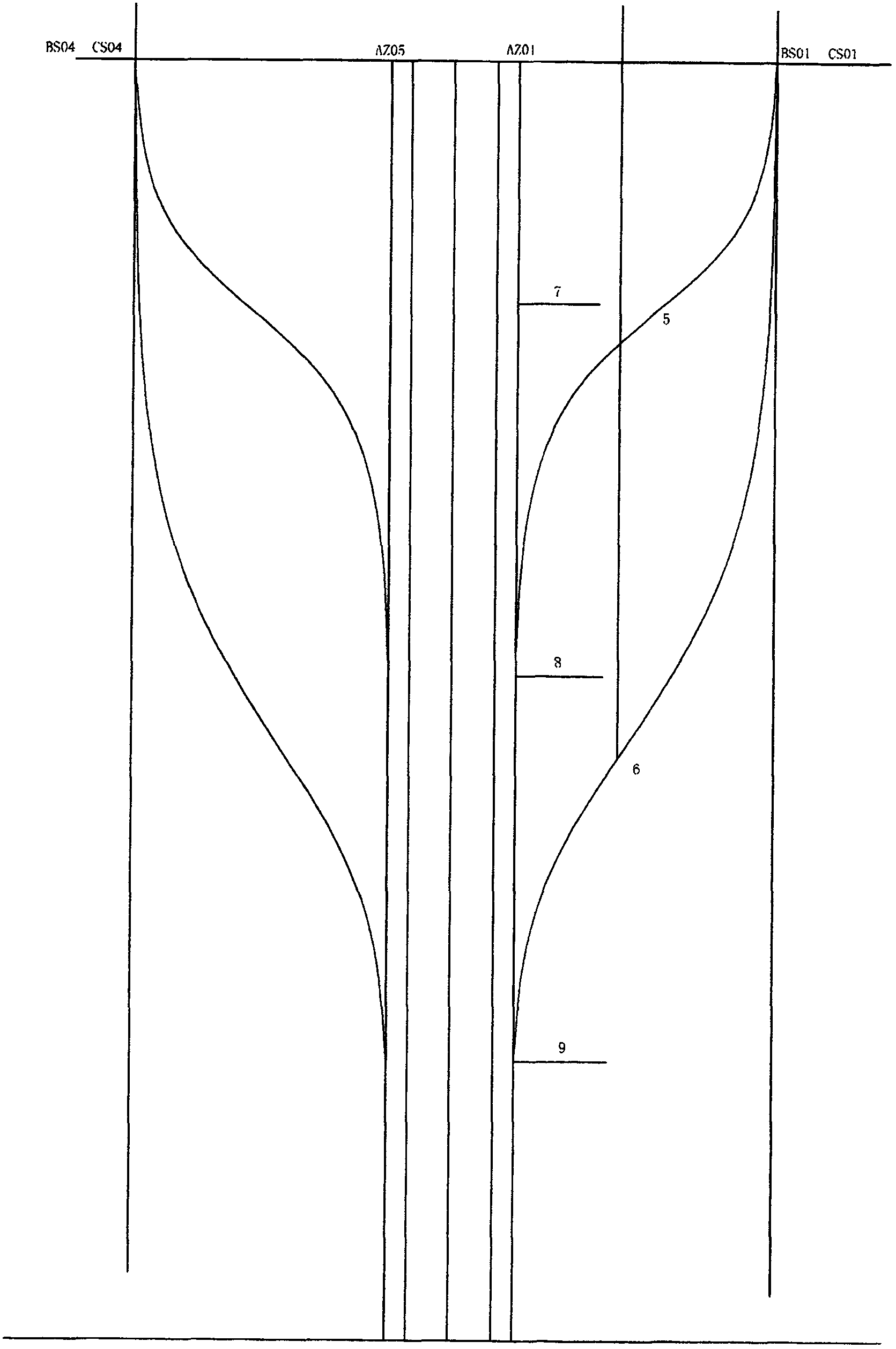
[0022] (2) The grouting holes in the second layer S are arranged at a distance of 40-60 meters away from the wellhead, and when the drilling depth reaches 480 meters, they are directed into the projection coordinates of the straight holes or evenly distributed at the projection of the diameter of the grouting circle of the straight holes. The initial grouting depth of the layer working face is 480 meters, and the final depth is 820 meters;

[0023] (3) The grouting holes of the third layer S are arranged 40-60 meters away from the wellhead, and when the drilling depth reaches 780 meters, they are directed into the projection coordinates of the straight holes or evenly d...


PUM


Abstract

The invention provides a multiple-working-face parallel working process for shaft ground pre-grouting. The process is accurate in positioning and high in working efficiency. The technical scheme includes that the process comprises the steps of implementing an innovative process route which is different from traditional grouting for ground pre-grouting, dividing a shaft into a plurality of working faces, conducting multi-section grouting, during 800-1000m ultra-deep shaft operation, according to field conditions, enabling the 200-300m section to serve as a main grouting section, and dividing the main grouting section into three layers, wherein the first layer is the straight-hole grouting section, the second layer is the S-hole grouting section, and the third layer is the S-hole grouting section. According to the process, the technology of a straight hole and multiple-working-face S holes is adopted, the parallel working process that the vertical shaft ground pre-grouting is divided into a plurality of portions for simultaneous construction is initiated, specific positions in traditional processes are not required to be adopted, parallel operation of construction such as freezing and shaft sinking is possible, while the quality is guaranteed, the construction speed is accelerated, and the shaft building cycle is shortened for construction units.

Description

technical field [0001] The invention relates to the technical field of pre-grouting, in particular to a multi-face parallel operation process for pre-grouting on the surface of a shaft. Background technique [0002] At present, domestic wellbore surface pre-grouting mainly includes two types of schemes: full straight hole and S hole. The traditional solution of straight hole grouting uses a water source drilling rig to drill the grouting hole, which occupies the position of the wellhead. Subsequent construction such as freezing or sinking can only be carried out after the grouting is completed. Parallel operations such as injection, freezing, and drilling cannot be performed. Relatively long, generally 800 to 1,000 meters of wellbore, the grouting cycle is about one and a half years. S-hole directional technology is relatively backward. The difficulty of S-hole construction technology lies in the inaccuracy of directional trajectory. This has a lot to do with the domestic s...

Claims


Application Information

Patent Timeline
Patent Type & Authority Applications(China)
IPC IPC(8): E21B33/138
Inventor 张新立齐吉龙曲来才
Owner 张新立
Why Eureka
Try Eureka