Display screen supporting frame with adjustable tilt angle

A technology of display screen and support frame, which is applied in the direction of machine table/support, support machine, mechanical equipment, etc., and can solve the problems of human insecurity, inconvenience, thick torsion spring, etc.

Active Publication Date: 2013-08-07
TAIZHOU STRONKIN ELECTRONICS
View PDF4 Cites 4 Cited by
  • Summary
  • Abstract
  • Description
  • Claims
  • Application Information

AI Technical Summary

Problems solved by technology

But the biggest shortcoming of this prior art is owing to have adopted torsion spring and be set on the thicker rotating shaft, and the installation length of rotating shaft that display screen can give is often limited again, and the quantity of torsion spring installation is also just limited, because To balance or resist the large gravitational component of the display screen, the torsion spring has to be made very thick, whether it is the diameter of the spring wire or the overall winding diameter, in order to generate enough balanced reaction force, resulting in the appearance of the whole machine at the local shaft. It is particularly bloated, which seriously affects the appearance of the display screen, especially the lightness and thinness. Especially for the more and more heavy all-in-one display screens currently used, the torsion spring will be thicker, and the situation will be more serious, especially for the current More and more pursuit of ultra-thin, fashionable model requirements, this is almost a fatal flaw, and of course it is not conducive to minimizing the packaging volume space; for this reason, some existing technologies have to increase the pressure of elastic components. Tighten the proportion of the friction force to reduce the proportion of the torsion spring force more to reduce the size of the torsion spring force, but after the friction force increases, the feet will be lifted up due to the friction force when the screen is lifted, and manual re-use is required. It is very inconvenient to forcibly press it on the desktop, so it can only be increased by a small amount and it will not help
What's more deadly is that when the legs of this type of support structure swing at a large angle, there is a big problem of the so-called "mouse trap" phenomenon, that is, when the legs swing relatively to the display screen , The spring will have a high-speed rebound impact due to sudden rebound. This is because the spring that is originally used to balance the weight of the display screen is in a tensioned state. Release (similar to a mousetrap), the greater the relative rotation angle, the more severe the impact; since the support frame is still firmly connected to the display screen, high-speed impact may easily cause damage to the display screen and produce a loud impact sound, which is also very unsafe for people
For this reason, there is a structure that increases friction to reduce its impact, and what is more, simply does not use springs and uses axial compression friction or at most a small amount of spring force. , when the screen is lifted up, the feet are also lifted by the friction force and separated from the table, so when the screen is lifted, you need to press the feet with your hands, and obviously the pressing force is the gravity component of the screen. Adding friction, that is, almost twice the gravity of the screen, such an operation, not to mention using force, is also very inconvenient and unnatural, especially with light, thin, fashionable and advanced modern electrical products. It feels extremely uncoordinated.
But so far, the above problems have not had a good solution

Method used


Image

  • Display screen supporting frame with adjustable tilt angle
  • Display screen supporting frame with adjustable tilt angle
  • Display screen supporting frame with adjustable tilt angle

Examples


Embodiment Construction

[0031] In order to make the technical means, creative features, goals and effects achieved by the present invention easy to understand, the present invention will be further described below in conjunction with specific embodiments.

[0032] The display screens of the present invention all include liquid crystal display screens, liquid crystal displays, liquid crystal all-in-one display screens, and liquid crystal monitors, which are collectively referred to as display screens or screens for simplicity.

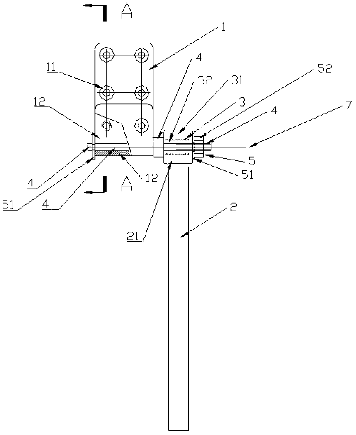
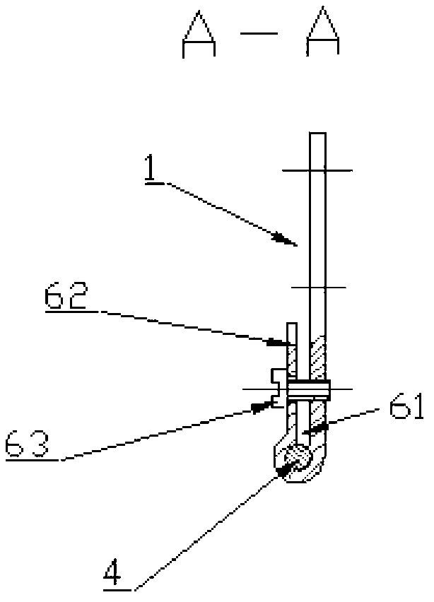
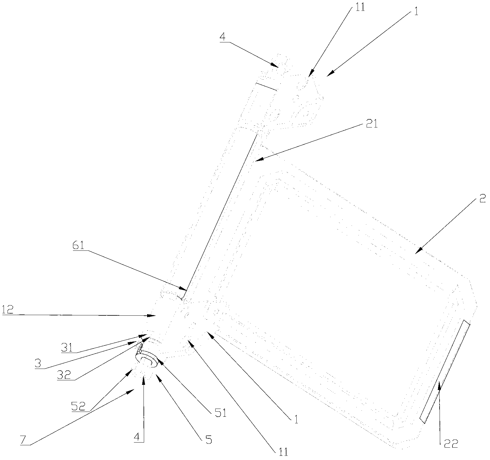
[0033] For this example see figure 1 , figure 2 , image 3 , Figure 4 , Figure 5 , Figure 6 As follows: a display screen support frame with adjustable inclination. It includes: a screen fixing part 1, the upper part of which is a fixing part 11, and the lower part is a pivot part 12. The fixing part 11 is in the shape of a plate and has a plurality of holes for connecting the screen. The known technology of fasteners such as screws is used. Or the technology known in...


PUM


Abstract

The invention relates to a display screen supporting frame with an adjustable tilt angle. In the prior art, torsional springs are sleeved on supporting leg rotating shafts to balance the screen weight, so that the defects that thick torsional springs are required, attractive appearances of whole machines are affected seriously, the hand feeling is poor, and 'mouse trap' phenomena of high-speed rebounding shocks of supporting legs exist, or the problem that operation is inconvenient and unnatural caused by the fact that supporting legs are required to be pressed by hand at the backs of screens due to the fact that supporting legs are raised by the friction force when screens are lifted exists. According to the display screen supporting frame, a unidirectional rotating clutch and transforming rotating friction are adopted, the spring force which serves as the main balance force is cancelled, a plurality of defects in the prior art are overcome, functions of normal balanced supporting, inclination angle adjustment and supporting leg retraction of a screen are implemented, supporting legs are close to a table board all the time when the screen is lifted, the specific 'mouse trap' phenomena of spring type structures or unnatural actions of pressing of supporting legs by hand are thoroughly eliminated, the operation is natural and convenient, and a comfortable usage and operation environment is provided for users.

Description

technical field [0001] The invention relates to a display screen support frame, in particular to a photo frame-type display screen support frame with adjustable inclination angle. Background technique [0002] When the display screen is in use, it is generally necessary to use the support frame on it to place the support and adjust the viewing angle. Therefore, the support frame is an inseparable important combination and supporting component of the display screen. A reasonable support frame structure can not only provide users with a better and more Comfortable use conditions can also set off a better appearance of the whole machine, so that the operation of the display screen can more perfectly meet the requirements of ergonomics, while minimizing the size, saving desktop space, easy to disassemble, and convenient for packaging and transport. [0003] In addition to a large type of support frame that is supported vertically on the table, another large type of display scr...

Claims


Application Information

Patent Timeline
Patent Type & Authority Applications(China)
IPC IPC(8): F16M11/10F16M13/02
Inventor 曲工栾连平
Owner TAIZHOU STRONKIN ELECTRONICS
Why Eureka
Try Eureka