Furnace end capable of discharging water and residue easily

A technology for removing residues and burners, which is applied in the field of burners that are easy to drain and discharge residues. It can solve the problems of increasing manufacturing costs, affecting ignition, and excessive exhaust gas emissions, so as to achieve comfortable use environment, improve efficiency, and reduce ambient temperature. Effect

Pending Publication Date: 2019-01-11
山东金佰特商用厨具有限公司
View PDF0 Cites 0 Cited by
  • Summary
  • Abstract
  • Description
  • Claims
  • Application Information

AI Technical Summary

Problems solved by technology

When the chef is cooking, it is inevitable to clean the pot or overflow the soup and residues. The water left when cleaning the pot or the overflowing soup and residues will flow into the combustion chamber along the outer wall of the pot. When the water Or when the soup and residue accumulate to a certain amount, it will have an adverse effect on the combustion of the gas in the combustion chamber, resulting in insufficient combustion of the gas and affecting the ignition, thereby making the exhaust gas discharge exceed the standard and causing environmental pollution
In order to solve this problem, some manufacturers of commercial stoves set up drains or connecting drains at the bottom of the combustion chamber, but the directly connected drains can not only drain water, but also the waste gas generated by the combustion of gas in the combustion chamber will follow the waste water through the drains. Exhaust, this part of the exhaust gas is directly discharged into the air and cannot be sucked away by the range hood above the stove, which makes the air quality in the use space where the stove is located deteriorates and affects the health of the chef
Moreover, the temperature of the exhaust gas generated by gas combustion is very high, and this part of the heat is discharged into the air through the drain pipe. First, the high-temperature exhaust gas seriously affects the life of the drain pipe, and the requirements for the drain pipe are very high, which increases the manufacturing cost; It will affect the life of the appliances of the stove, and at the same time make the temperature of the space where the stove is used remain high, making the working environment of the chef even worse

Method used


Image

  • Furnace end capable of discharging water and residue easily

Examples


Embodiment Construction

[0014] Below in conjunction with accompanying drawing embodiment, the present invention will be further described:

[0015] In this embodiment, the flow direction of the air in the main ventilation pipe 4 is taken as the rear, and vice versa as the front.

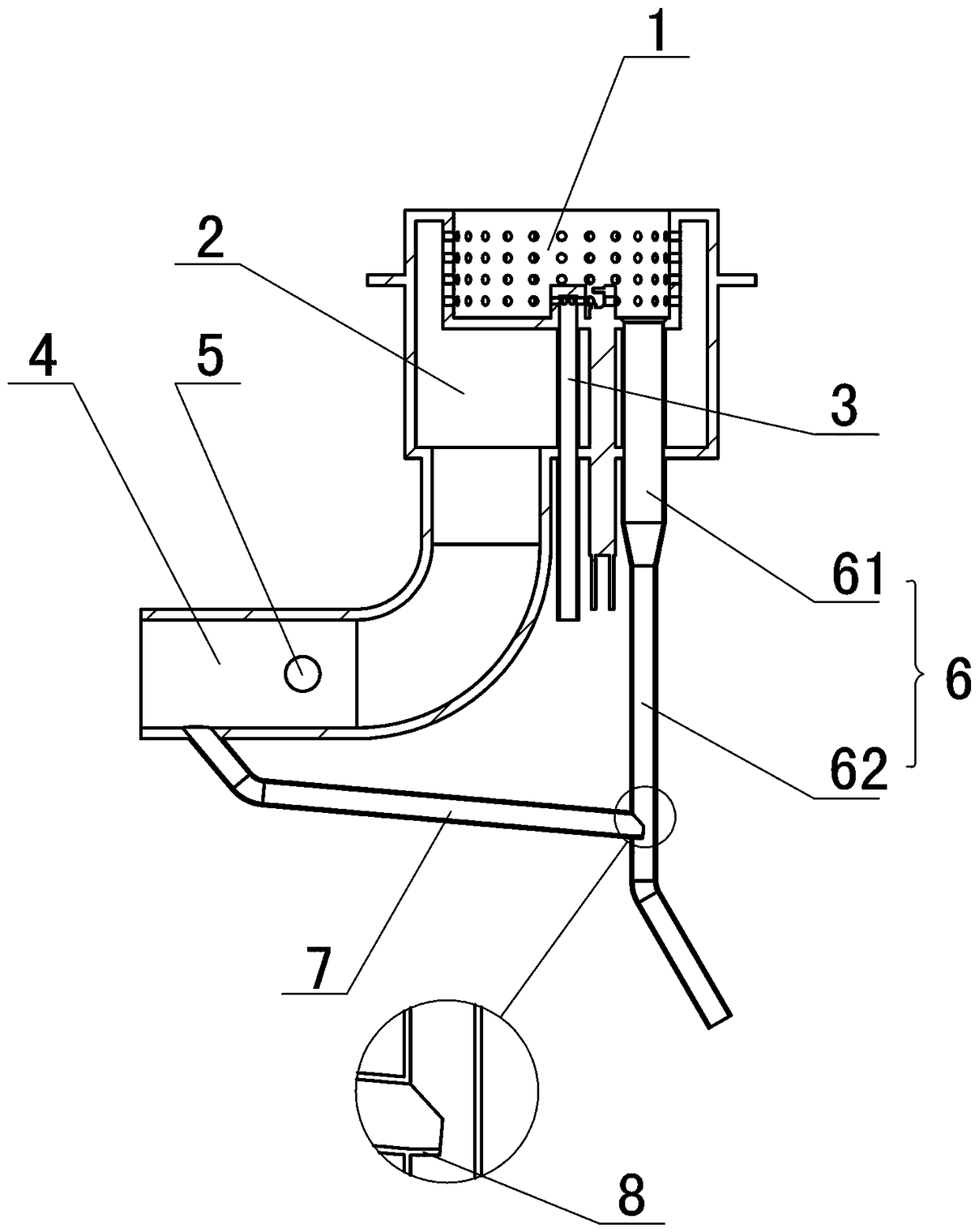
[0016] Such as figure 1 As shown, the present invention provides a burner that is easy to drain and discharge residues, including a combustion chamber 1 and an air mixing chamber 2 communicated with the combustion chamber 1. In this embodiment, the combustion chamber 1 is located inside the air mixing chamber 2, and the combustion chamber 1 The side wall is provided with a number of ventilation holes, and the bottom of the combustion chamber 1 is connected with a kindling inlet pipe 3 . The wind and air mixing chamber 2 is also communicated with the main fire ventilation pipe 4, and the main fire ventilation pipe 4 is provided with a main fire air inlet 5. The bottom of combustion chamber 1 communicates with drainpipe 6, ...


PUM


Abstract

The invention discloses a furnace end capable of discharging water and residue easily and belongs to the field of commercial kitchen ware. The furnace end comprises a tinder gas inlet pipe, a main fire ventilating pipe, a combustion chamber and a wind-gas blending cavity communicating with the combustion chamber. The tinder gas inlet pipe communicates with the combustion chamber. The main fire ventilating pipe communicates with the wind-gas blending cavity. A main fire gas inlet is formed in the main fire ventilating pipe. The bottom of the combustion chamber communicates with a water discharging pipe. The furnace end is characterized in that the main fire ventilating pipe communicates with the water discharging pipe through a wind taking pipe, the wind taking pipe is located at the frontend of the main fire gas inlet, and the end, close to the main fire ventilating pipe, of the wind taking pipe is higher than the end, close to the water discharging pipe, of the wind taking pipe. By means of the furnace end, wastewater in the combustion chamber can be effectively discharged, and in addition, waste gas can be prevented from being exhausted through a water discharging outlet.

Description

technical field [0001] The invention belongs to the field of commercial kitchen utensils, and in particular relates to a burner that is easy to drain and discharge residues. Background technique [0002] Commercial stoves are widely used in restaurants, hotels and other occasions, and most of them use liquefied petroleum gas to provide heat. At present, the ignition method of existing commercial stoves is usually the ignition mode of the constant fire and the main fire. When the stove is in normal use, the gas and air are firstly mixed uniformly in the air mixing chamber and then burnt in the combustion chamber, thereby heating the pan above the combustion chamber. When the chef is cooking, it is inevitable to clean the pot or overflow the soup and residues. The water left when cleaning the pot or the overflowing soup and residues will flow into the combustion chamber along the outer wall of the pot. When the water Or when the soup and residue accumulate to a certain amount...

Claims


Application Information

Patent Timeline
Patent Type & Authority Applications(China)
IPC IPC(8): F23D14/02F23D14/46
CPCF23D14/02F23D14/46
Inventor 徐清东
Owner 山东金佰特商用厨具有限公司
Why Eureka
Try Eureka