Light emitting diode (LED) bulb

A technology of LED light bulbs and LED light sources, applied in the field of LED lighting, can solve the problems of small lighting angles of LED lights, and achieve the effect of avoiding dark areas

Active Publication Date: 2013-08-07
SICHUAN LIANKAI LIGHTING CO LTD
View PDF7 Cites 11 Cited by
  • Summary
  • Abstract
  • Description
  • Claims
  • Application Information

AI Technical Summary

Problems solved by technology

Therefore, a dark area will be generated at the bottom of the lampshade, so that the overall light emitting angle of the LED lamp is small

Method used


Image

  • Light emitting diode (LED) bulb

Examples


Embodiment Construction

[0012] The present invention will be further described in detail below in conjunction with the accompanying drawings and specific embodiments.

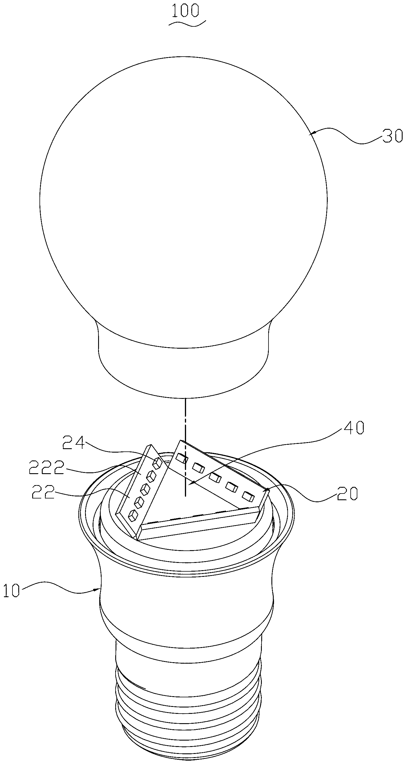
[0013] figure 1 It is an exploded perspective view of an LED bulb 100 according to the first embodiment of the present invention. The LED bulb 100 includes a lamp body 10 , three light source panels 20 , a bulb shell 30 , and a reflector 40 . The light source panels 20 and the reflector 40 are arranged on the top surface of the lamp body 10 , and the bottom of the bulb shell 30 is fixed on the top of the lamp body 10 to store the light source panels 20 and the reflector 40 inside.

[0014] Please refer to figure 1 , these LED light source boards 20 are ceramic substrates, and each light source board 20 includes a substrate 22 and a plurality of LED light sources 24 . The front surface 222 of the substrate 22 is provided with a reflective layer (not shown in the figure), and the reflective layer is used to reflect part of the light e...


PUM


Abstract

The invention discloses an LED bulb. The LED bulb comprises a bulb holder, a bulb case and at least three light source plates, wherein the top of the bulb holder is covered with the bottom of the bulb case, each of the light source plates is provided with an LED light source on the front side, the front of each light source plate faces towards the bottom of the bulb case, the light source plates are arranged at the top of the bulb holder annularly, fronts of the light source plates are arranged oppositely, and heights of the light source plates are lower than that of the bottom of the bulb case. The LED bulb has the advantage of even light emitting.

Description

technical field [0001] The invention relates to the field of LED lighting, in particular to an LED light bulb. Background technique [0002] As the third generation lighting source, LED light source has been widely used in indoor lighting. In recent years, more and more people hope to make LED light sources similar to incandescent lamps. However, due to the inherent luminous characteristics of LED light sources, they cannot achieve the luminous angle of incandescent lamps, making it difficult for LED bulbs to completely replace incandescent lamps. For example, the Chinese invention patent application with the application number 201110264489.X with the publication date of 2012.01.25 discloses an LED lamp, which includes a lamp body, a heat sink, an LED lamp board and a lampshade. The LED lamp The board includes LED light sources and a base plate. The LED light sources are laid flat on the base plate. The base plate is arranged on the top of the lamp body and is covered by th...

Claims


Application Information

Patent Timeline
Patent Type & Authority Applications(China)
IPC IPC(8): F21S2/00F21V19/00F21Y101/02F21K9/232F21K9/235F21Y115/10
Inventor 李甫文
Owner SICHUAN LIANKAI LIGHTING CO LTD
Why Eureka
Try Eureka