
Gas drainage pipeline parameter measuring method

A technology for parameter measurement and gas drainage, applied in measuring devices, measuring fluid pressure, pressure difference measurement between multiple valves, etc., can solve the problem of no integrated temperature probe, unstable differential pressure measurement, long pressure hose Jitter and other problems, to reduce the influence of human factors, lower the lower limit of measurement, and avoid signal fluctuations

Active Publication Date: 2015-06-03
CHINA COAL TECH & ENG GRP CHONGQING RES INST CO LTD
View PDF6 Cites 0 Cited by
  • Summary
  • Abstract
  • Description
  • Claims
  • Application Information

AI Technical Summary

Problems solved by technology

[0002] At present, the flow measurement principle of portable pipeline parameter measuring instruments on the market is mostly the principle of differential pressure measurement. The pressure induction tube is inserted into the pipeline to be tested, and then the fluid in the pipeline to be tested is introduced into the back-end host through the long pressure induction hose. , converted into an electrical signal and then processed, which is easy to introduce interference, such as the vibration of the long pressure hose leads to unstable differential pressure measurement, and the temperature signal is disturbed, etc.
And there is no integrated temperature probe. When measuring the temperature, the temperature measuring device needs to be inserted into the pipeline to be treated separately.

Method used


Image

  • Gas drainage pipeline parameter measuring method
  • Gas drainage pipeline parameter measuring method

Examples


Embodiment Construction

[0018] The present invention will be further described below in conjunction with drawings and embodiments.

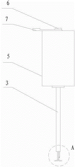
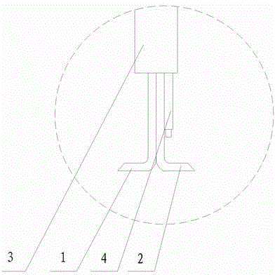
[0019] The gas drainage pipeline parameter measurement method includes a parameter measuring instrument. The parameter measuring instrument includes a measuring device and a pitot tube connected to the fluid signal input port of the measuring device. The pitot tube includes a protective tube 3, a hollow L-shaped pressure guiding tube I1 and Hollow L-shaped pressure guide tube II2, one end of pressure guide tube I1 and pressure guide tube II2 is the inlet port, the other end of pressure guide tube I1 and pressure guide tube II2 is the fluid signal output port, the inlet port of pressure guide tube I1 and the guide port The direction of the inlet port of the pressure tube II2 is opposite, the fluid signal output ports of the pressure guiding tube I1 and the pressure guiding tube II2 are connected to the fluid signal input port of the measuring device, and the protective tu...


PUM


Abstract

The invention discloses a gas drainage pipeline parameter measuring method. A parameter measuring gauge is utilized in the gas drainage pipeline parameter measuring method and comprises a measuring device and a pitot pipe connected at a fluid signal input port of the measuring device, and the pitot pipe comprises a protective pipe, a hollow L-shaped pressure leading pipe I and a hollow L-shaped pressure leading pipe II. The gas drainage pipeline parameter measuring method specifically includes the steps of (1) vertically inserting the pressure leading pipe I and the pressure leading pipe II into a pipeline to be measured, and enabling a leading-in port of the pressure leading pipe I or the pressure leading pipe II to be right opposite to flowing direction of fluid in the pipeline; (2) reading physical signals led in by the pressure leading pipe I and the pressure leading pipe II, converting the physical signals into analog electric signals, and converting the analog electric signals into digital signals after being amplified and filtered; and (3) leading the digital signals into a host computer so as to display parameters of the measured pipeline. By the gas drainage pipeline parameter measuring method, signal fluctuation and interference caused by an over-length physical signal transmission channel and trembling of the physical signal transmission channel are avoided, stability of measurement data is improved, lower limit of flow measurement is lowered, human factors are reduced, ceaseless-flow online mounting and utilizing can be realized, mounting is facilitated, and utilization is simple.

Description

technical field [0001] The invention relates to a pipeline measurement method, in particular to a gas pipeline parameter measurement method. Background technique [0002] At present, the flow measurement principle of portable pipeline parameter measuring instruments on the market is mostly the principle of differential pressure measurement. The pressure induction tube is inserted into the pipeline to be tested, and then the fluid in the pipeline to be tested is introduced into the back-end host through the long pressure induction hose. , converted into an electrical signal and then processed, which is easy to introduce interference, such as the vibration of the long pressure hose leads to unstable differential pressure measurement, and the temperature signal is disturbed. And there is no integrated temperature probe. When measuring the temperature, the temperature measuring device needs to be inserted into the pipeline to be treated separately. Contents of the invention ...

Claims


Application Information

Patent Timeline
Patent Type & Authority Patents(China)
IPC IPC(8): G01L9/00G01L13/06
Inventor 莫志刚王璇李涛胡超孙世岭罗前刚路萍
Owner CHINA COAL TECH & ENG GRP CHONGQING RES INST CO LTD
Learn More