Supercharge Your Innovation With Domain-Expert AI Agents!

Optical fiber bidirectional multi-fire-head control system

A control system and burner technology, applied in the laser field, can solve the problems of low coupling efficiency and easy bending deformation of fiber couplers, and achieve the effects of stable flame temperature, uniform heating increase, and avoiding fiber bending

Active Publication Date: 2013-08-07
北京同方华光系统科技有限公司
View PDF4 Cites 0 Cited by
  • Summary
  • Abstract
  • Description
  • Claims
  • Application Information

AI Technical Summary

Problems solved by technology

[0005] The technical problem to be solved by the present invention is how to provide an optical fiber bidirectional multi-fire head control system to overcome the defect in the prior art that the heated optical fiber is easily bent and deformed, resulting in low coupling efficiency of the optical fiber coupler

Method used


Image

  • Optical fiber bidirectional multi-fire-head control system
  • Optical fiber bidirectional multi-fire-head control system
  • Optical fiber bidirectional multi-fire-head control system

Examples


Embodiment 1

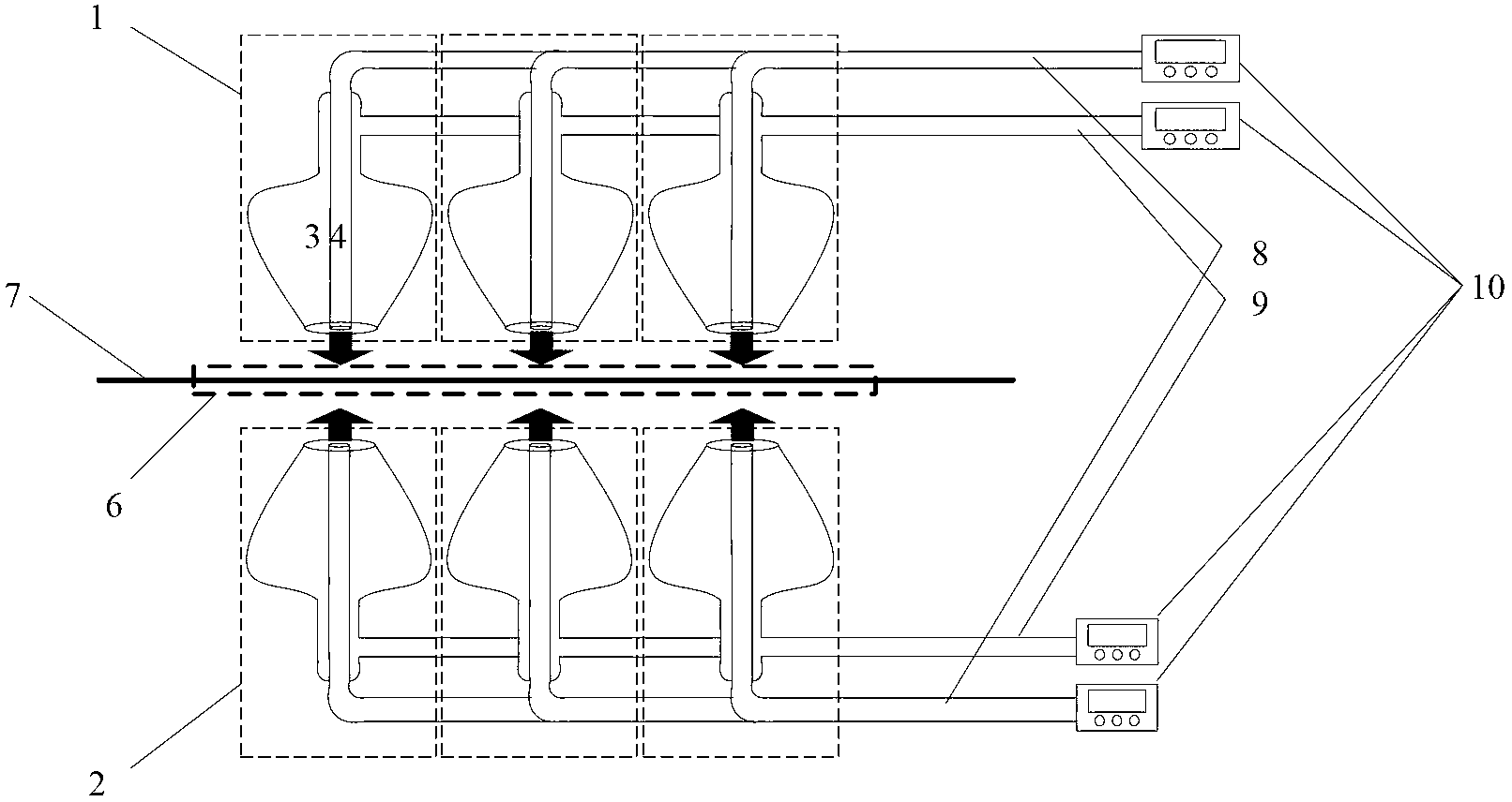
[0023] like figure 1 As shown, the optical fiber bidirectional multi-fire head control system provided by the embodiment of the present invention includes: a plurality of upper fire heads 1 and a plurality of lower fire heads 2 arranged oppositely on the upper and lower sides, each of the upper fire heads 1 and the lower fire heads 2 is fed with combustible gas The pipeline 8 and the combustion-supporting pipeline 9; wherein the combustible gas 3 passes through the combustible gas pipeline 8; the combustion-supporting gas 4 passes through the combustion-supporting pipeline 9.

[0024] The combustible gas pipeline 8 and the gas-supporting pipeline 9 are respectively connected to the gas flow controller 10 for regulating and controlling the gas flow; The gas control quantities of the pipeline 8 and the gas-supporting pipeline 9 are independent of each other and are not affected by each other.

[0025] The lower heating head and the upper heating head heat the optical fiber thro...

Embodiment 2

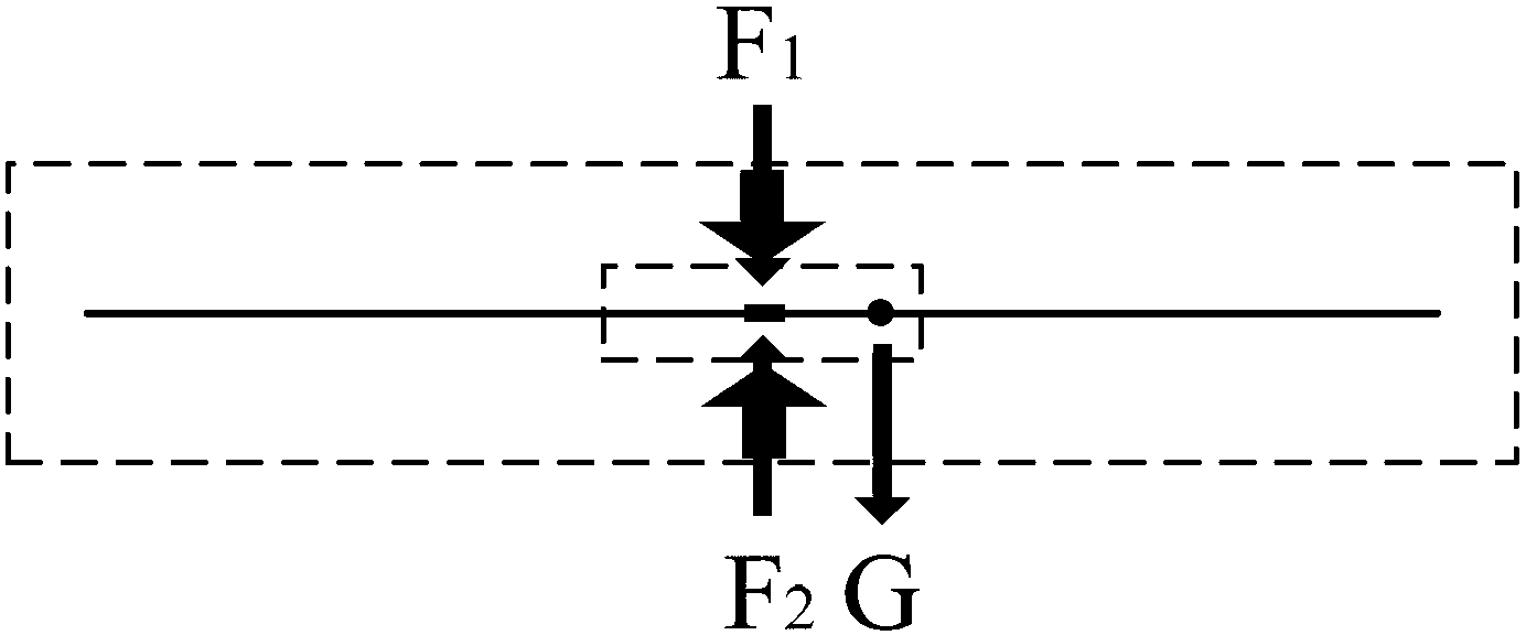
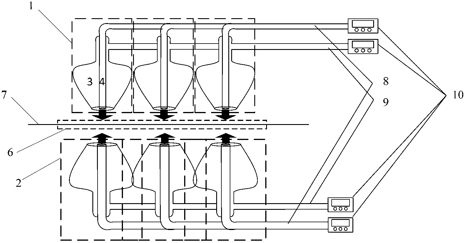
[0029] like image 3 As shown, the difference between the present embodiment and the first embodiment is that the diameter of the nozzle of the lower fire head 2 is larger than that of the top fire head 1 in this embodiment. By adjusting the gas flow controller 10, the gas flow in the combustible gas pipeline 8 and the gas-supporting pipeline 9 in the lower firing head 2 is equal to the gas flow in the combustible gas pipeline 8 and the supporting gas pipeline 9 in the heating head 1 . The gas density ejected from the lower burner 2 and the gas pressure on the optical fiber in the combustion zone 6 are stronger than that of the upper burner, so that the optical fiber in the combustion zone 6 produces an upward force. At the same time, due to the downward gravity of the optical fiber itself, the optical fiber subjected to the upward force and its own downward gravity cancel each other out, so that the optical fiber is placed stably in a horizontal posture, which can effectively...


PUM


Abstract

The invention relates to the technical field of laser, in particular to an optical fiber bidirectional multi-fire-head control system for getting rid of gravity. The control system comprises a plurality of upper fire heads and a plurality of lower fire heads which are opposite. Each upper fire head and each lower fire head are communicated into a flammable gas pipeline and a combustion-supporting gas pipeline. The flammable gas pipeline and the combustion-supporting gas pipeline are respectively connected to a gas flow controller. The lower fire heads and the upper fire heads heat an optical fiber upwardly and the downwardly respectively. By the control system, the optical fiber can be stably placed horizontally, and the problem of severe deformation such as optical fiber bending caused by self-gravity of the optical fiber during manufacturing of an optical fiber coupler is solved. Controllable gas density adjusting of multiple fire head nozzles allows flame temperature in a combustion area to be relatively stable, the to-be-heated optical fiber remains in a stable temperature field always, and accordingly the optical fiber in the combustion area is heated evenly, and coupling efficiency of optical fiber couplers is improved.

Description

technical field [0001] The invention relates to the field of laser technology, in particular to an optical fiber two-way multi-fire control system freed from the constraints of gravity. Background technique [0002] Compared with the traditional fiber laser composition firmware processing, the manufacturing process of fiber coupler is extremely complicated, the technical field involved is relatively wide, and the technical difficulties that need to be overcome are relatively complicated. In the manufacturing process of the fiber coupler, the device that causes the fiber to be melted and coupled by heating is an extremely critical and core component. Today, these components include: Omega rings, bidirectional burners, unidirectional burners, laser heating and irradiation, and other methods. The purpose of these heating methods is to effectively control the heating temperature so that the optical fiber is heated evenly during the process of melting and coupling. Stablize. ...

Claims


Application Information

Patent Timeline
Patent Type & Authority Applications(China)
IPC IPC(8): G02B6/255
Inventor 闫平肖起榕陈霄巩马理
Owner 北京同方华光系统科技有限公司
Features
  • R&D
  • Intellectual Property
  • Life Sciences
  • Materials
  • Tech Scout
  • Unparalleled Data Quality
  • Higher Quality Content
  • 60% Fewer Hallucinations
Learn More