
Small volume electrical connector assembly and its plug and socket

An electrical connector, small-volume technology, applied in the parts, connections, electrical components and other directions of the connecting device, can solve the problem that it is difficult to meet the requirements of miniaturization and portability, the electrical connector components are difficult to meet the requirements of vibration, impact, electrical components, etc. Problems such as bloated connector components

Active Publication Date: 2015-08-26
CHINA AVIATION OPTICAL-ELECTRICAL TECH CO LTD
View PDF2 Cites 0 Cited by
  • Summary
  • Abstract
  • Description
  • Claims
  • Application Information

AI Technical Summary

Problems solved by technology

[0002] In the current high-density electrical connectors, most of them use a plug to match a socket. When users require that the plug and socket can be plugged in modularly, each plug can be locked with the socket or removed from the socket. , the requirements for use cannot be met
The reason is mainly because the locking mechanism in high-density small electrical connectors is too large compared to the connector, especially in products with small cores. If the current locking mechanism (each plug and The sockets are locked with threads or bayonet sockets), when a socket is equipped with multiple small-core plugs and each plug can be removed and locked, the overall electrical connector assembly will appear extremely bloated, and it is difficult to meet small If the relatively small barb structure is adopted, it will make it difficult for the electrical connector assembly to meet the vibration and shock requirements.

Method used


Image

  • Small volume electrical connector assembly and its plug and socket
  • Small volume electrical connector assembly and its plug and socket
  • Small volume electrical connector assembly and its plug and socket

Examples


Embodiment Construction

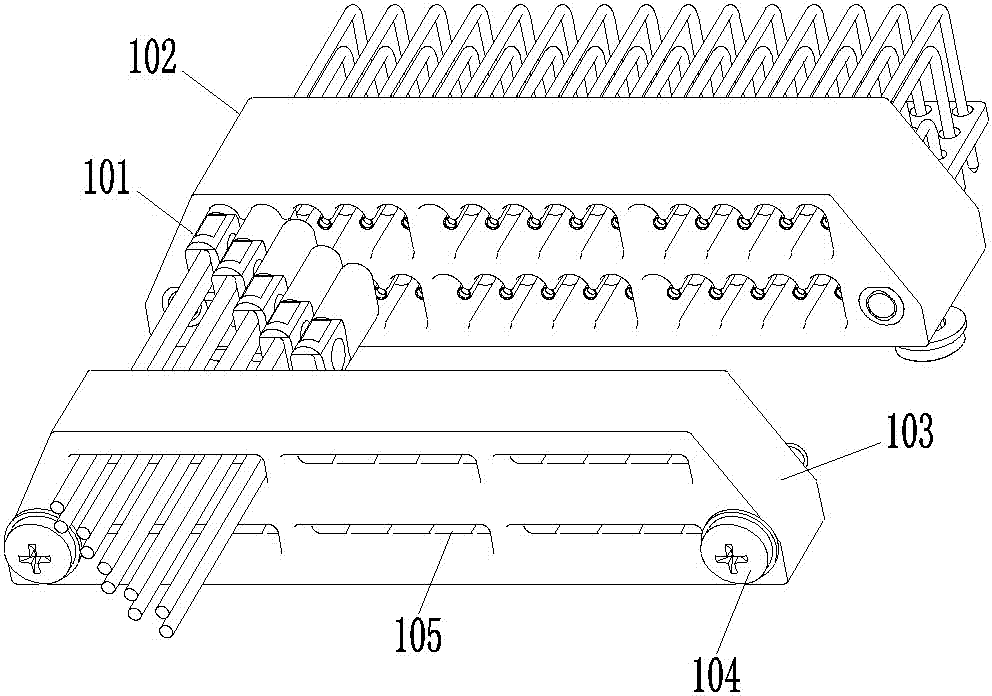
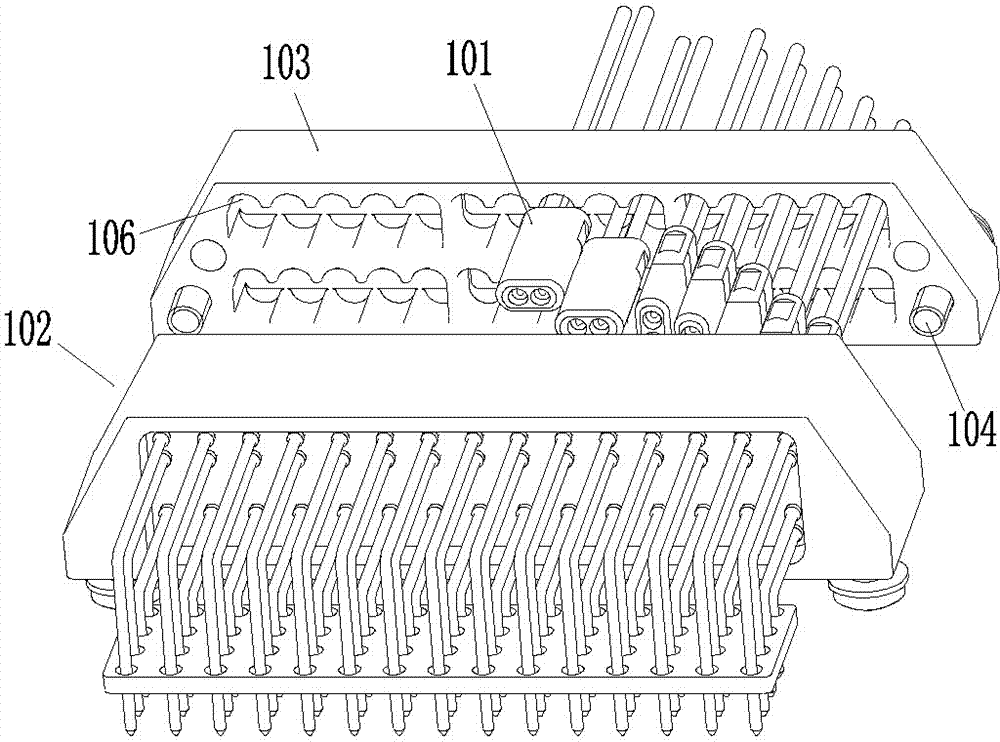
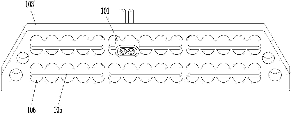
[0022] Examples of low volume electrical connector assemblies, such as Figure 1-3 As shown, it includes a plug 101 and a socket. In this embodiment, there are several plugs 101 and they are matched with the socket 102. The matching of the plug 101 and the socket 102 here means that each plug can find a matching plug on the socket. Each plug can be mated with the socket at the same time.

[0023] The plug 101 uses the front end as the plug-in end, which includes a plug shell, which is in the shape of a cuboid and has a backstop. The so-called backstop is a structure that cooperates with the socket 102 to prevent the plug from being automatically disengaged relative to the socket. In an example, the stop portion of the plug 101 is formed by its rear end surface.

[0024] The socket 102 uses the front end as the plug-in end, which has a socket shell, and a pressure plate 103 is fixedly mounted on the plug-in end of the socket shell, and the pressure plate 103 is detachably moun...


PUM


Abstract

The invention relates to the field of electric couplers, in particular to a small-size electric coupler component, plugs thereof and a plug seat thereof. The small-size electric coupler component comprises the plug seat and the plugs matched with the plug seat. The plugs are provided with plug shells, and the plug seat is provided with a plug-seat shell. A press plate is detachably and fixedly assembled at the front end of the plug-seat shell. Sockets are arranged on the press plate. The plug seat has an inserting structure inserted with the plugs after corresponding plugs are inserted into the sockets and rotated by a set angle. Stopping portions used for being in abutted fit with the inner surface of the press plate after the plugs are inserted into the plug seat are arranged on the plug shells. Most of a locking structure of the small-size electric coupler component is integrated on the plugs and the plug seat, and a sole external locking component (the press plate) can lock multiple plugs simultaneously, so that the small-size electric coupler component is small in size and simple in structure; and meanwhile, locking between the plugs and the plug seat is realized by the 'compacting' of the press plate, so that strength is extremely easy to guarantee, and vibration-proof and anti-loose requirements can be met easily.

Description

technical field [0001] The invention relates to the field of electrical connectors, in particular to a small-volume electrical connector assembly and its plug and socket. Background technique [0002] In the current high-density electrical connectors, most of them use a plug to match a socket. When users require that the plug and socket can be plugged in modularly, each plug can be locked with the socket or removed from the socket. , the usage requirements cannot be met. The reason is mainly because the locking mechanism in high-density small electrical connectors is too large compared to the connector, especially in products with small cores. If the current locking mechanism (each plug and The sockets are locked with threads or bayonet sockets), when a socket is equipped with multiple small-core plugs and each plug can be removed and locked, the overall electrical connector assembly will appear extremely bloated, and it is difficult to meet small If a relatively small bar...

Claims


Application Information

Patent Timeline
Patent Type & Authority Patents(China)
IPC IPC(8): H01R13/639H01R13/46H01R24/00
Inventor 张磊
Owner CHINA AVIATION OPTICAL-ELECTRICAL TECH CO LTD
Learn More