Power switch cabinet

A technology of switchgear and electric power, applied in the field of electric switchgear, which can solve the problems of high humidity in the operating environment of equipment in the cabinet, moisture exchange and evaporation, threats to safe operation of equipment, etc., and achieve low cost, good dehumidification, maintenance and repair low cost effect

Inactive Publication Date: 2013-08-07
STATE GRID CORP OF CHINA +1
View PDF7 Cites 7 Cited by
  • Summary
  • Abstract
  • Description
  • Claims
  • Application Information

AI Technical Summary

Problems solved by technology

[0010] It can be seen from the above table that the dehumidification capacity of the existing heating and dehumidification device is only 0.45H% / m 3 h, the dehumidification effect is not ideal, and the moisture cannot be evaporated through the exchange of internal and external air, resulting in high humidity in the operating environment of the equipment in the cabinet, which poses a great threat to the safe operation of the equipment

Method used


Image

  • Power switch cabinet
  • Power switch cabinet
  • Power switch cabinet

Examples


Embodiment

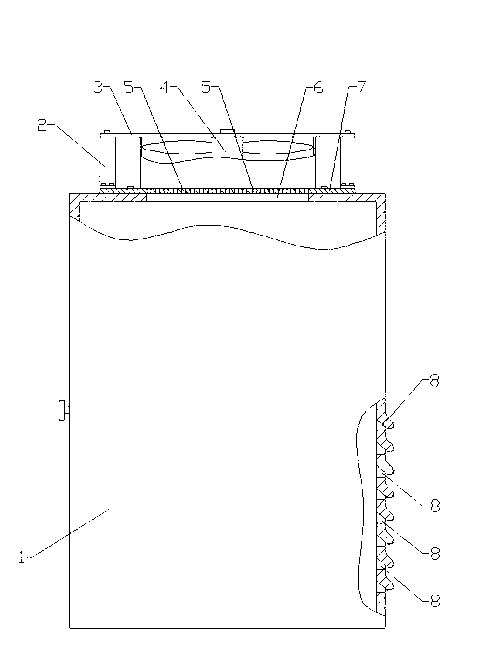
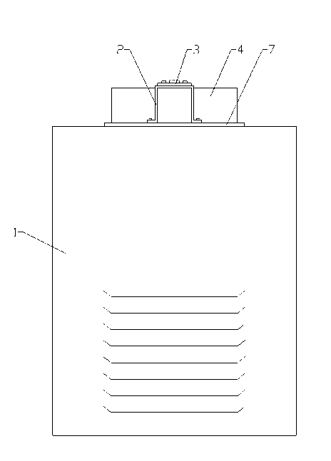
[0038] Example: as attached figure 1 And attached figure 2 As shown, the switch cabinet for electric power includes a cabinet body 1, and the cabinet body 1 is provided with an air inlet 8 and an air outlet hole 5, and an air exhaust device 4 is arranged at the air outlet hole 5.

[0039] The air inlet 8 is located at the rear of the cabinet body 1 .

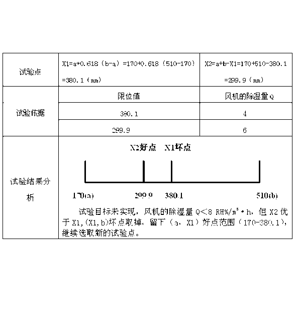
[0040] Choice of air inlet 8 positions:

[0041]

[0042]

[0043] It can be seen from the above table that the air inlet 8 is located at the rear of the cabinet body 1, which has the best dehumidification effect and the largest safety distance.

[0044] The air inlet 8 is set at the rear of the cabinet 1, and the dehumidification effect is better than that of the air inlet 8. It is set at the top and front of the cabinet 1, which will not pose a safety threat to the operator, and the distance from the equipment in the cabinet 1 is also safe Require.

[0045] Air inlet 8 is the windproof louver air inlet.

[0046] C...


PUM


Abstract

The invention relates to a power switch cabinet which comprises a cabinet body. The cabinet body is provided with an air inlet and an air outlet. An exhauster is disposed at the air outlet. Since the cabinet body is provided with the air inlet and the air outlet and the exhauster is disposed at the air outlet, the exhauster operates to exhaust vapor in the cabinet body when the interior humidity of the cabinet reaches a set value. Dehumidification capacity is fine, arcing discharging in moving and fixed contacts is avoided, the service lives of power devices are prolonged, and maintenance cost is low.

Description

technical field [0001] The invention relates to an electric power equipment, in particular to an electric power switch cabinet. Background technique [0002] The electrical switchgear currently used is usually designed with airtightness. This is for the consideration of preventing small animals from entering and damaging the power facilities. The natural ventilation of the switch cabinet is poor, which hinders air convection, and the moisture cannot be discharged in time, resulting in high ambient humidity in the cabinet, which may easily cause discharge between the dynamic and static contacts of the switch, resulting in damage to electrical components. [0003] Taking the 35kV mid-mounted switchgear as an example, since the moisture in the cabinet cannot be discharged, the dynamic and static contacts of the switch are burned. The contact burn accident is caused by the arc discharge of the dynamic and static contacts due to the high humidity in the cabinet. [0004] The mai...

Claims


Application Information

Patent Timeline
Patent Type & Authority Applications(China)
IPC IPC(8): H02B1/56
Inventor 赵琪刘振德魏吉超程立浩刘永辉曾芳王晓健左景强张广新
Owner STATE GRID CORP OF CHINA
Why Eureka
Try Eureka