Capacity discharge method and circuit

A capacitor discharge circuit and capacitor discharge technology, applied in the field of power supply, can solve the problem of high energy consumption, and achieve the effect of reducing power loss, reducing no-load power consumption and standby power consumption, and meeting power consumption requirements.

Active Publication Date: 2015-07-08
SILERGY SEMICON TECH (HANGZHOU) CO LTD
View PDF5 Cites 0 Cited by
  • Summary
  • Abstract
  • Description
  • Claims
  • Application Information

AI Technical Summary

Problems solved by technology

[0004] In view of this, the present invention provides a capacitor discharge method and a discharge circuit, which are applied to switching power supplies to solve the problem of high energy consumption caused by X capacitor discharge circuits in switching power supplies in the prior art

Method used


Image

  • Capacity discharge method and circuit
  • Capacity discharge method and circuit
  • Capacity discharge method and circuit

Examples


Embodiment Construction

[0041] Several preferred embodiments of the present invention will be described in detail below with reference to the accompanying drawings, but the present invention is not limited to these embodiments. The present invention covers any alternatives, modifications, equivalent methods and schemes made on the spirit and scope of the present invention. In order to provide the public with a thorough understanding of the present invention, specific details are set forth in the following preferred embodiments of the present invention, but those skilled in the art can fully understand the present invention without the description of these details.

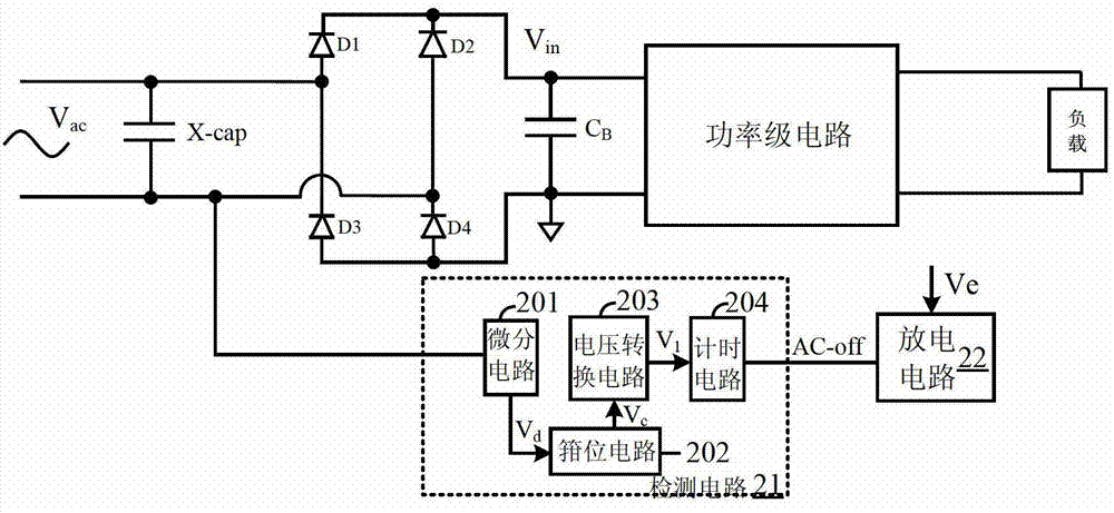
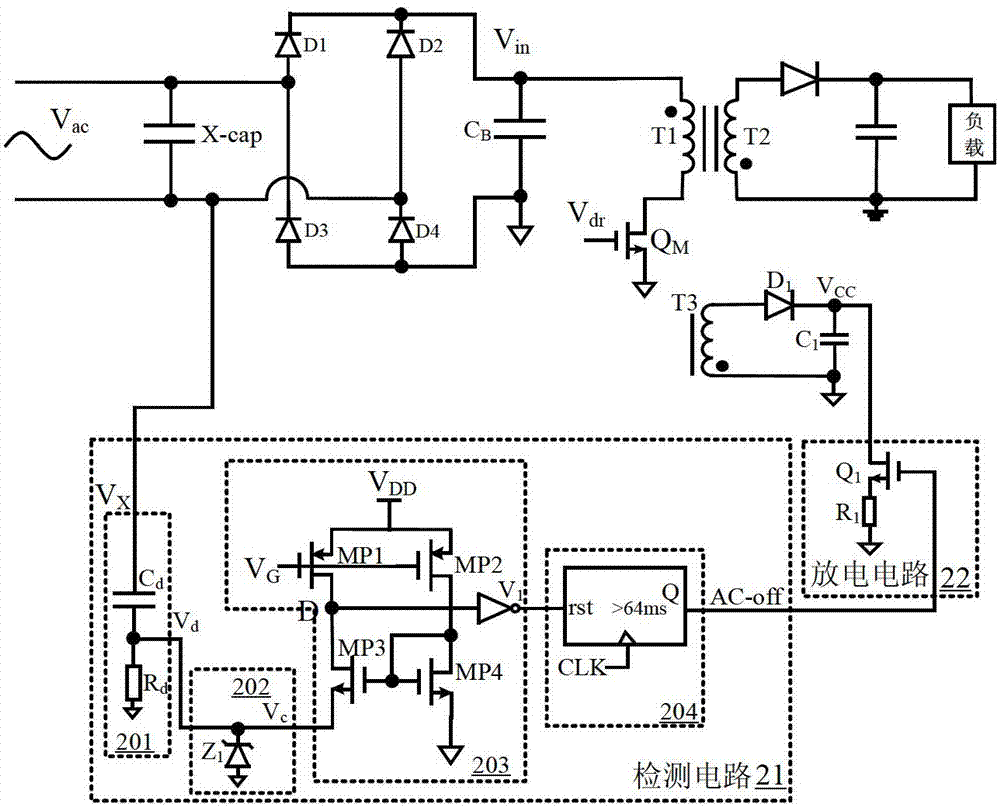
[0042] refer to figure 2 , is shown as a functional block diagram of a capacitor discharge circuit according to the present invention, which is applied in a switching power supply, and the switching power supply includes an X capacitor connected between the input terminals of the switching power supply, a rectifier bridge circuit compose...


PUM


Abstract

In one embodiment, a method of controlling a capacitor discharge for a switching power supply, can include: (i) generating a first voltage signal from a voltage at an X capacitor that is coupled between input terminals of the switching power supply; (ii) activating a detection signal in response to the first voltage signal being inactive for a duration of a predetermined time interval, where the detection signal being activated indicates a cut-off of the input terminals; and (iii) at least partially discharging the X capacitor after the cut-off and in response to activation of the detection signal.

Description

technical field [0001] The invention relates to the field of power supplies, more specifically, to a capacitor discharge method and a discharge circuit applied to switching power supplies. Background technique [0002] At the input end of the AC power supply of the switching power supply, an X capacitor is generally connected in parallel between the live wire and the neutral wire as a safety capacitor to suppress EMI conduction interference (mainly to suppress differential mode interference). In some occasions, due to actual needs, The capacitance of the X capacitor is often relatively large, so that after the AC power is cut off, the X capacitor will store high-voltage electric energy for a long time, and the safety standard stipulates that within two seconds after the AC power is cut off, the voltage of the input terminal of the power supply must drop to 30% of the original rated working voltage, so in order to meet the requirements of safety standards, the X capacitor nee...

Claims


Application Information

Patent Timeline
Patent Type & Authority Patents(China)
IPC IPC(8): H02M3/07
CPCH02M1/32H02M2001/322H02M1/322H02M3/335H02M3/33507
Inventor 黄秋凯韩云龙徐孝如
Owner SILERGY SEMICON TECH (HANGZHOU) CO LTD
Why Eureka
Try Eureka