Single-suction single-stage centrifugal fan with medium-high pressure and medium-large flow

A centrifugal fan and high pressure technology, which is applied to the components of the pumping device for elastic fluid, mechanical equipment, radial flow pump, etc. question

Pending Publication Date: 2019-03-08
ZHENJIANG DANTU DISTRICT FOOD FACTORY
View PDF0 Cites 0 Cited by
  • Summary
  • Abstract
  • Description
  • Claims
  • Application Information

AI Technical Summary

Problems solved by technology

[0002] Centrifugal fan is a general-purpose equipment widely used. Its main function is to convert electrical energy into wind energy. It has the characteristics of simple structure and convenient manufacture, because its main function is to use wind, that is, the flow of air to meet the needs of various processes, such as ventilation and ventilation. , Dust reduction, drying, cooling, combustion, material transportation, etc., involving all aspects of industry and civil use, with the development of industry and the increasing complexity of modern process routes, the construction of industrial houses and the increase of environmental protection equipment and environmental protection devices , so that the process effect of using low-pressure fans in some original processes is very poor, because the resistance of the pipe network increases, and the fans need to overcome the resistance before the fans can effectively do work, and the fans at their performance points can be found in the national standard samples. However, its power dis...

Method used


Image

  • Single-suction single-stage centrifugal fan with medium-high pressure and medium-large flow
  • Single-suction single-stage centrifugal fan with medium-high pressure and medium-large flow
  • Single-suction single-stage centrifugal fan with medium-high pressure and medium-large flow

Examples


Embodiment Construction

[0016] The high-pressure, medium-to-large-flow single-suction single-stage centrifugal fan of the present invention will be further described in detail below in conjunction with the accompanying drawings and specific embodiments.

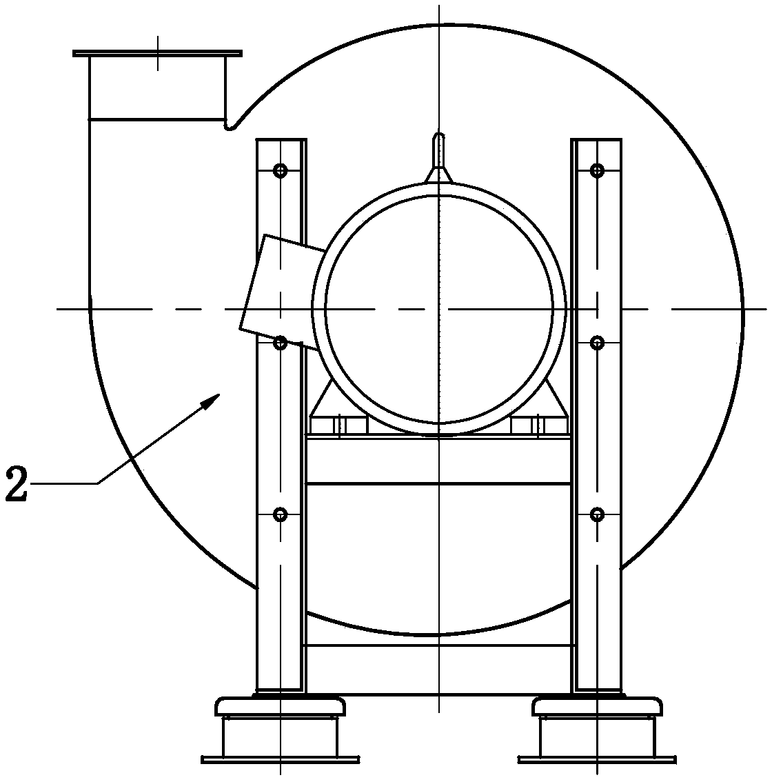
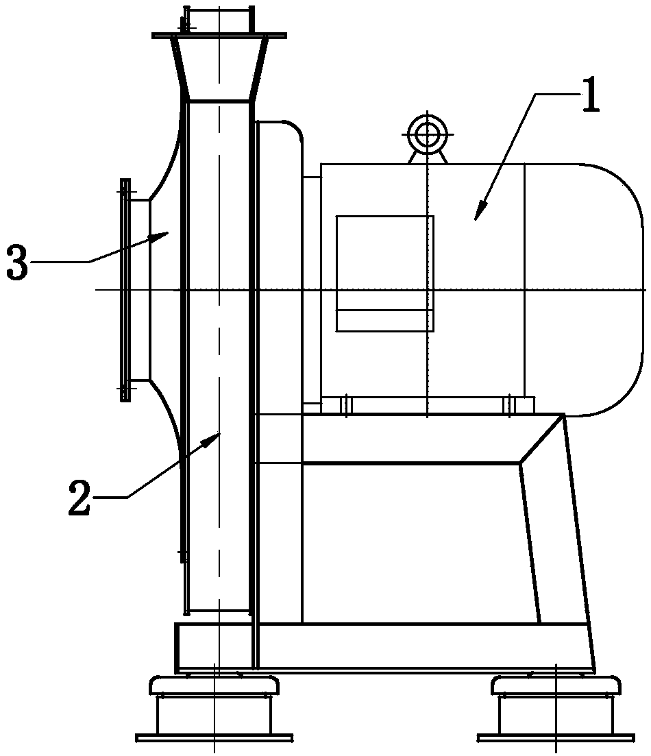
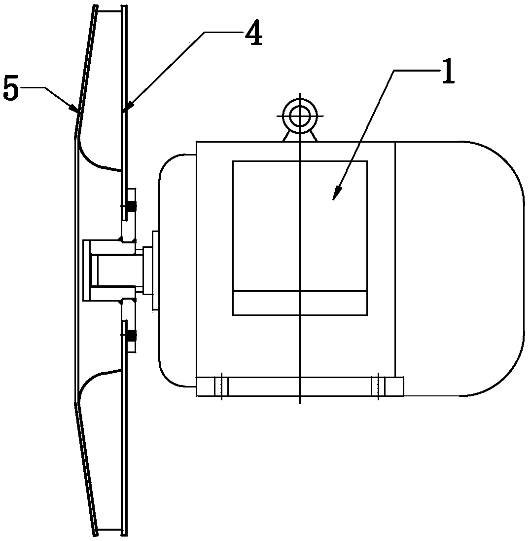
[0017] As shown in the figure, the high pressure, medium and large flow rate single-suction single-stage centrifugal fan of the present invention includes a driving motor 1, a casing 2 and an air inlet ring 3, the main shaft of the driving motor extends into the casing and an impeller 4 is installed. , it can be seen from the figure that the main shaft of the driving motor 1 extends into the casing, and a flange is fixedly installed on a shaft sleeve, and then the flange is installed on the rear end surface of the impeller, thereby completing the fixing with the impeller Installation, this installation structure makes the connection strength high, very reliable, greatly improves the service life and is conducive to the improvement of air tightness, a...


PUM


Abstract

The invention discloses a single-suction single-stage centrifugal fan with medium-high pressure and medium-large flow. The single-suction single-stage centrifugal fan comprises a driving motor, a machine shell and an air inlet ring. A main shaft of the driving motor extends into the machine shell and is provided with an impeller. The machine shell is arranged of a volute-shaped structure, the airinlet ring is of a trumpet-shaped structure, and a trumpet opening of the air inlet ring is fixedly installed on the front side of the machine shell. Backward bending type blades are arranged on the end surface of the impeller, each of the blades has an angle inclined from the periphery towards the center of the impeller as viewed from the side end faces, and each blade is bent on the inner side of the impeller to form an-arc shaped flange and enable the center of the impeller to form a trumpet-shaped opening. After adopting the structure, the flow is greatly improved, the flow capacity is greatly improved, the structural design is very compact, the size is small, a production material is saved, the requirements for energy consumption of the fan are met, the space for energy saving is verylarge, an integral support structure is achieved, and the overall structural strength and operational stability are further improved.

Description

technical field [0001] The invention relates to a centrifugal fan, in particular to a single-suction single-stage centrifugal fan with high pressure and medium and large flow. Background technique [0002] Centrifugal fan is a general-purpose equipment widely used. Its main function is to convert electrical energy into wind energy. It has the characteristics of simple structure and convenient manufacture, because its main function is to use wind, that is, the flow of air to meet the needs of various processes, such as ventilation and ventilation. , Dust reduction, drying, cooling, combustion, material transportation, etc., involving all aspects of industry and civil use, with the development of industry and the increasing complexity of modern process routes, the construction of industrial houses and the increase of environmental protection equipment and environmental protection devices , so that the process effect of using low-pressure fans in some original processes is very...

Claims


Application Information

Patent Timeline
IPC IPC(8): F04D17/16F04D25/08F04D29/28F04D29/30F04D29/42F04D29/44F04D29/62F04D29/66
CPCF04D17/16F04D25/08F04D29/281F04D29/30F04D29/4226F04D29/441F04D29/626F04D29/668
Inventor 徐洋
Owner ZHENJIANG DANTU DISTRICT FOOD FACTORY
Why Eureka
Try Eureka