Steam turbine stator blade and steam turbine
A technology for steam turbines and stationary blades, applied in the direction of machines/engines, supporting components of blades, mechanical equipment, etc., can solve problems such as the inability to obtain sliding contact areas, and achieve the effect of suppressing self-excited vibration
- Summary
- Abstract
- Description
- Claims
- Application Information
AI Technical Summary
Problems solved by technology
Method used
Image
Examples
no. 1 approach
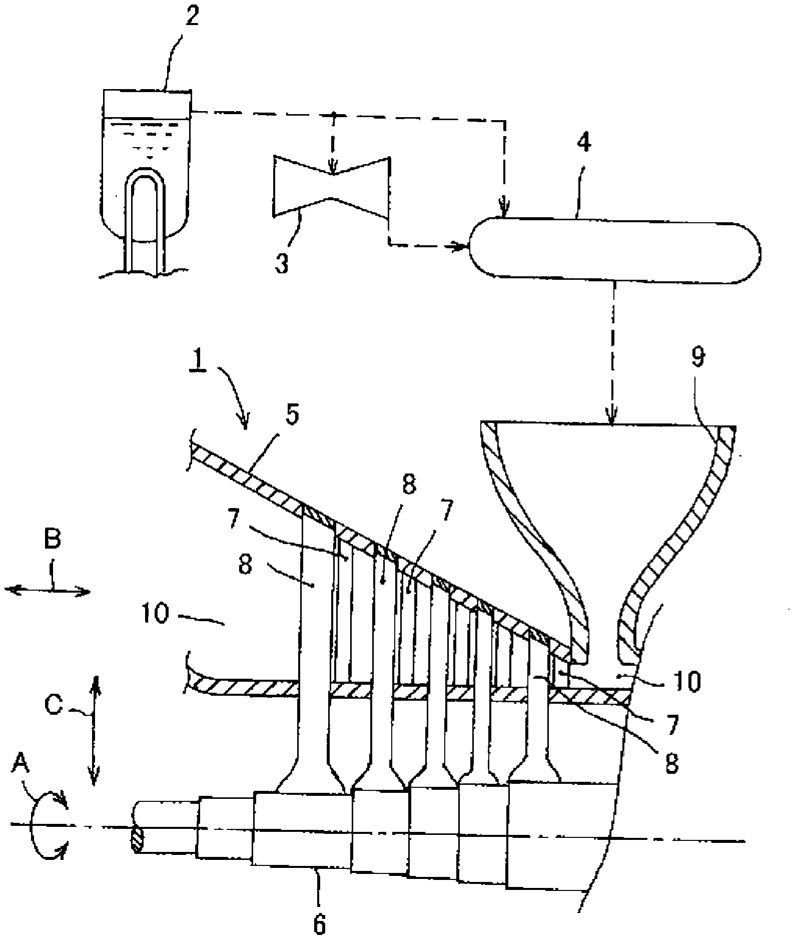
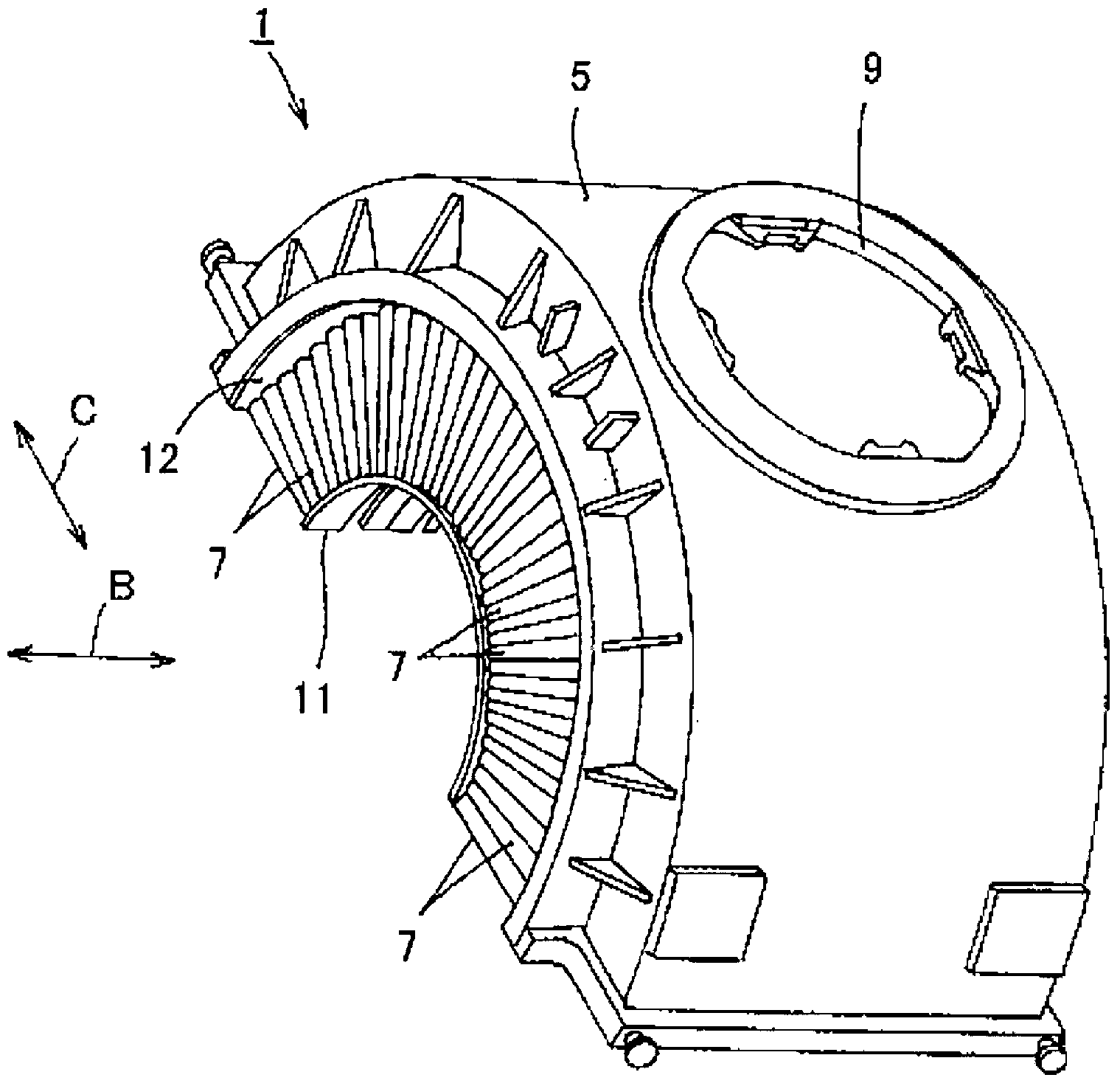
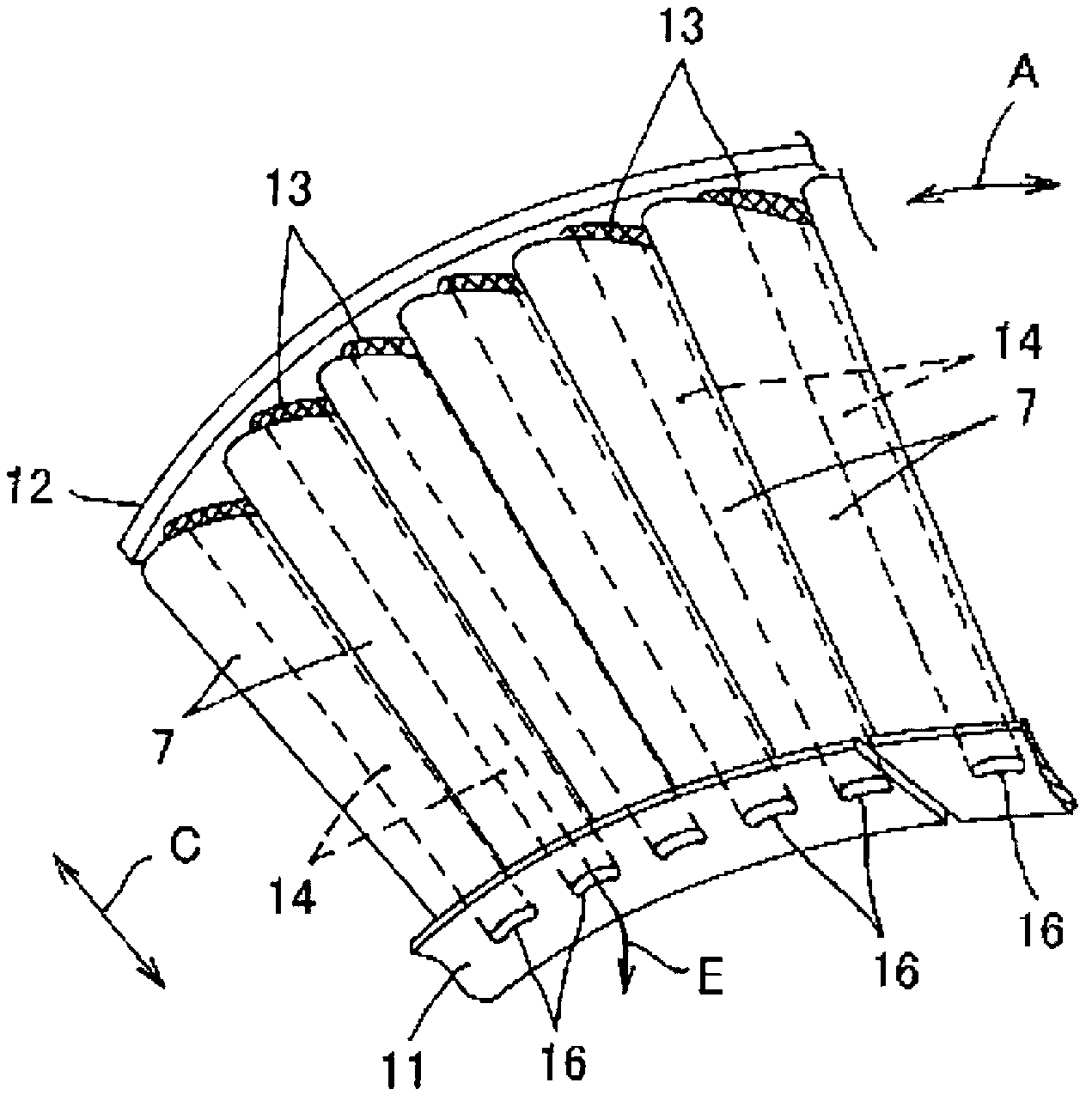
[0049] Figure 1 to Figure 3 A first embodiment of the steam turbine according to the present invention is shown. Figure 4 to Figure 9 The first embodiment of the stator blade of the steam turbine according to the present invention is shown. Next, the first embodiment of the steam turbine and the first embodiment of the stator blade of the steam turbine will be described respectively.
[0050] [Description of Steam Turbine 1]
[0051] exist figure 1 In , symbol 1 is the steam turbine in the first embodiment. The steam turbine 1 is, for example, a steam turbine used in a nuclear power plant. The nuclear power plant includes: a steam generator 2 that generates high-pressure steam, a high-pressure steam turbine 3 that directly supplies high-pressure steam from the steam generator 2, and separates moisture from the steam from the steam generator 2 and the high-pressure steam turbine 3 The moisture separation heater 4 that heats it, and the low-pressure steam turbine (low-pre...
no. 2 approach
[0081] Figure 10 A second embodiment of the steam turbine stator blade according to the present invention is shown. Next, the stator blade of the steam turbine according to the second embodiment will be described. in the figure, with Figure 1 to Figure 9 The same symbols in the symbols represent the same part.
[0082] In the above-described first embodiment, the stator blade 7 of the steam turbine is composed of a single leaf spring member. In contrast, the stator blades 7 of the steam turbine in the second embodiment, such as Figure 10 As shown, the leaf spring member 190 is divided into a plurality of blade members 17, 18 in the longitudinal direction. roughly equal contact area) into nine slices. That is, the positioning portion 27 is divided into a plurality (nine) by the groove 32 together with the elastic contact portion 28 and the connection portion 29 of the leaf spring member 190 .
[0083] The stator blade 7 of the steam turbine according to the second embo...
no. 3 approach
[0086] Figure 11 (A) and (B) show the third embodiment of the stator blade of the steam turbine according to the present invention. Next, the stator blade of the steam turbine according to the third embodiment will be described. in the figure, with Figure 1 to Figure 10 The same symbols in the symbols represent the same part.
[0087] In the steam turbine stator blades 7 according to the first and second embodiments described above, the leaf spring members 19 and 190 are divided into a plurality (nine pieces) by the grooves 32 having substantially equal widths, and divided into a plurality (nine pieces) The contact areas of the elastic contact portions 28 of the leaf spring members 19 and 190 are substantially equal to the inner surface 22 of the back member 18 (the contact area of the elastic contact portion 28 on the tip side is slightly different from the contact area of the other elastic contact portions 28 ). . On the other hand, in the stator blade 7 of the ste...
PUM
 Abstract
Description
Claims
Application Information
 - R&D Engineer
- R&D Manager
- IP Professional
- Industry Leading Data Capabilities
- Powerful AI technology
- Patent DNA Extraction
Browse by: Latest US Patents, China's latest patents, Technical Efficacy Thesaurus, Application Domain, Technology Topic, Popular Technical Reports.
© 2024 PatSnap. All rights reserved.Legal|Privacy policy|Modern Slavery Act Transparency Statement|Sitemap|About US| Contact US: help@patsnap.com


