Tightening and positioning tooling of crankshaft pulley of engine

A crankshaft pulley and positioning tooling technology, applied in workpiece clamping devices, manufacturing tools, etc., can solve problems such as difficult positioning and large torque, and achieve the effect of eliminating easy breakage, reducing costs, saving costs and downtime.

Inactive Publication Date: 2015-01-28
SAIC-GM-WULING AUTOMOBILE CO LTD
View PDF8 Cites 0 Cited by
  • Summary
  • Abstract
  • Description
  • Claims
  • Application Information

AI Technical Summary

Problems solved by technology

[0004] The technical solution of the present invention is to provide an engine crankshaft pulley tightening and positioning tool for the deficiencies of the prior art, which effectively solves the difficult positioning problem caused by the large torque of the crankshaft pulley tightening

Method used


Image

  • Tightening and positioning tooling of crankshaft pulley of engine
  • Tightening and positioning tooling of crankshaft pulley of engine

Examples


Embodiment Construction

[0022] Embodiments of the present invention will be described below with reference to the accompanying drawings.

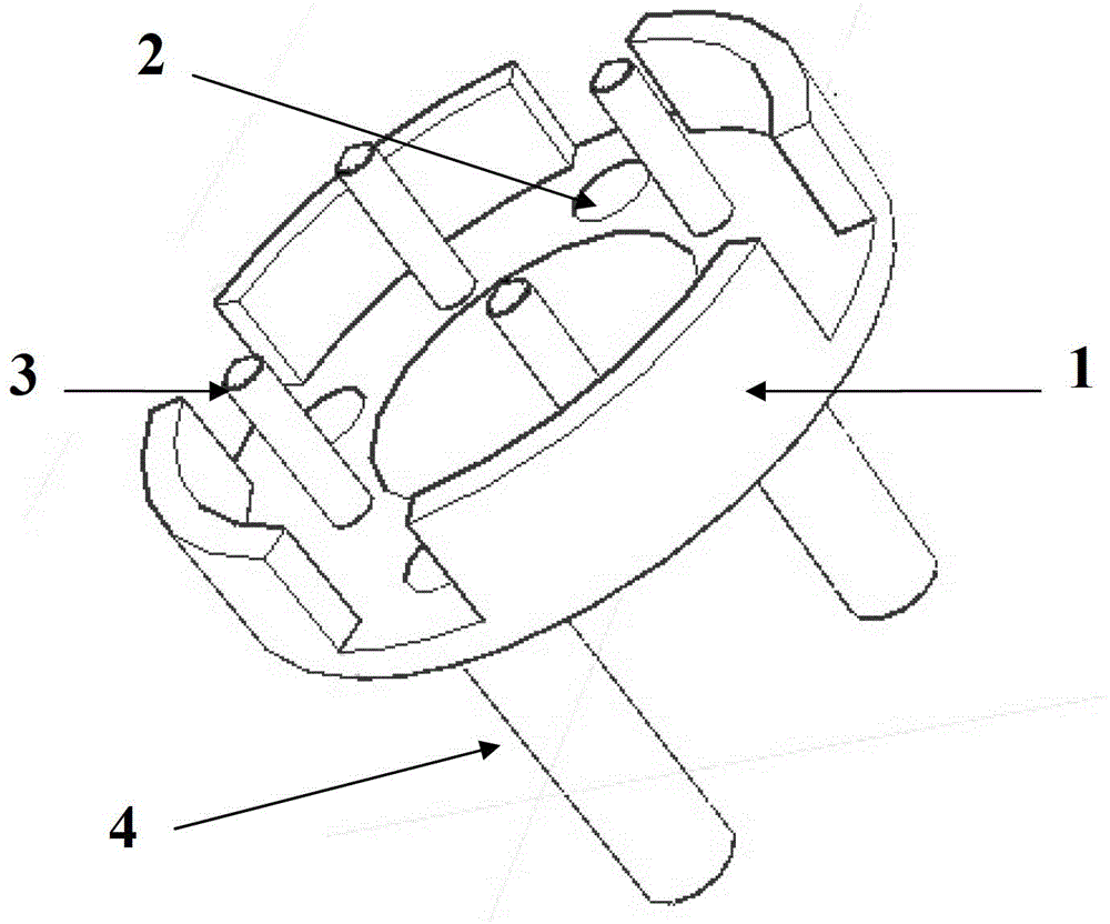
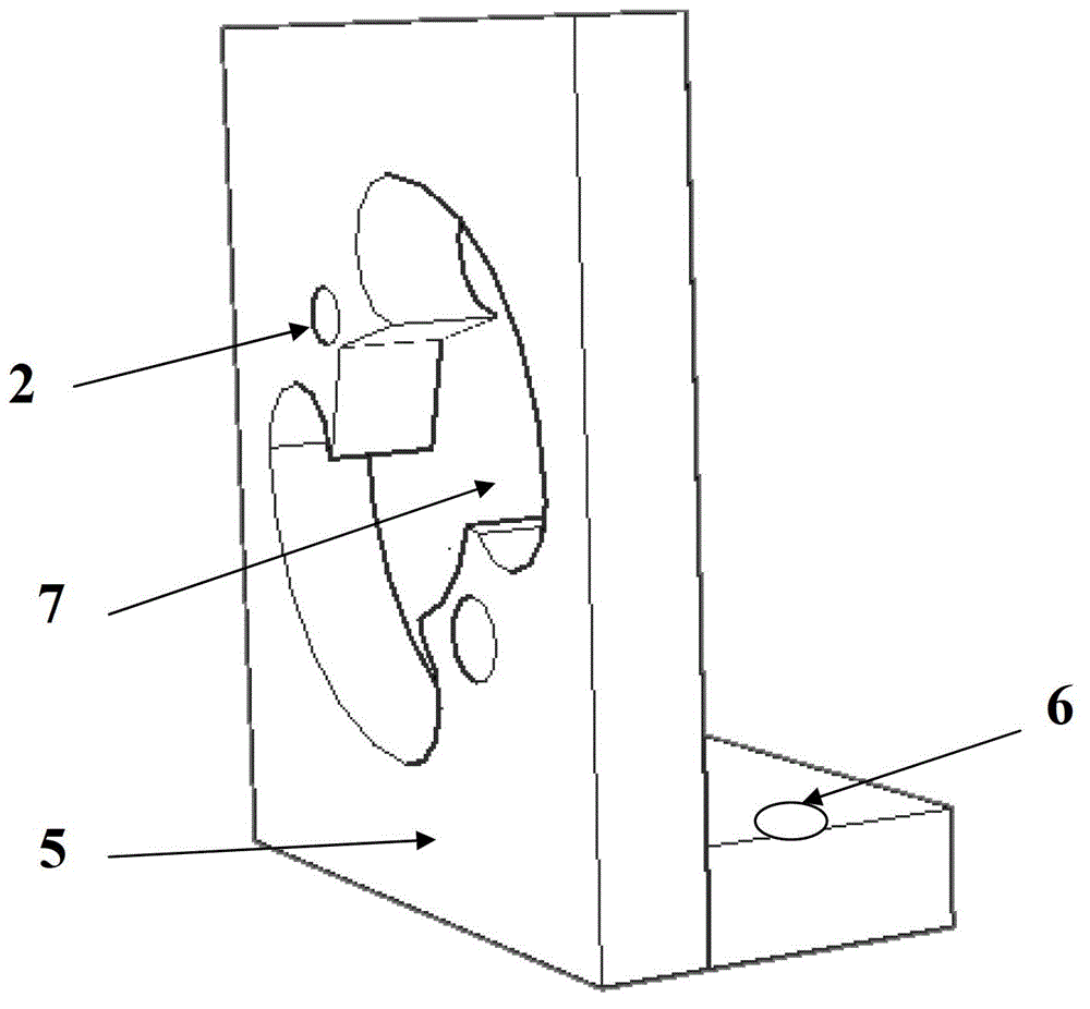
[0023] The engine crankshaft pulley tightening and positioning tool according to the present invention includes an L-shaped limit bracket 5, a free part of the tool, and a magnet installed on the L-shaped limit bracket 5 and the free part of the tool; the tool is free Part of the annular surface is provided with a magnet mounting hole 2, the edge of the annular surface is provided with a limit edge 1 protruding to one side, the side is also provided with a positioning pin 3, and the other side of the annular surface is provided with a limit claw. 4; the vertical surface of the L-shaped limit bracket 5 is provided with a magnet mounting hole 2 and a claw-shaped limit hole for holding the limit claw 4. The L-shaped limit bracket 5 has a There are bolt holes 6 connected to the front end of the stun gun bracket on the horizontal plane.

[0024] The limit edge 1 of th...


PUM


Abstract

A tightening and positioning tooling of a crankshaft pulley of an engine comprises an L-shaped limiting support, a tooling free portion and magnets. The magnets are arranged on the L-shaped limiting support and the tooling free portion; a toroidal surface of the tooling free portion is provided with magnet installing holes; the edge of the toroidal surface is provided with limiting sides protruding towards one side which is provided with positioning pins; the other side of the toroidal surface is provided with limiting claws; a vertical surface of the L-shaped limiting support is provided with the magnet installing holes and claw-shaped limiting holes; the claw-shaped limiting holes are used for placing the limiting claws; a horizontal surface of the L-shaped limiting support is provided with a blot hole which is connected with the front end of an electric gun support; and the magnets are embedded in the magnet installing holes in an interference matching mode. The tightening and positioning tooling of the crankshaft pulley of the engine has the advantages of effectively solving the original problem that different degrees of damages are caused to a flywheel threaded hole due to the fact that the flywheel threaded hole of a large end face of a crankshaft is utilized to perform positioning, substantially reducing costs and stop-line time and improving the level of on-line quality control.

Description

technical field [0001] The invention relates to a tightening and positioning tool for a crankshaft pulley of an engine. Background technique [0002] The crankshaft pulley is a part of the engine and is fastened to the front end of the crankshaft by bolts. When the stun gun is tightened, the dynamic torque is 95N.M+ (55°±4), and the static torque of the B15 model even reaches 200N.M. [0003] During the assembly process, since the crankshaft pulley is connected to the crankshaft, the pulley is easy to "follow" when tightening. The torque of the B15 model is especially large when tightening. The positioning pin" is inserted into the positioning threaded hole of the flywheel on the large end face of the crankshaft, and the copper "locating pin" is stuck to the limit when tightening; however, the flywheel threaded hole is often damaged due to the strong impact force at the end of tightening; Under the impact force, it will break after a few tightenings. Unable to meet the nee...

Claims


Application Information

Patent Timeline
Patent Type & Authority Patents(China)
IPC IPC(8): B25B11/02
Inventor 袁震
Owner SAIC-GM-WULING AUTOMOBILE CO LTD
Why Eureka
Try Eureka