Precise worm and gear

A worm gear and worm, precision technology, applied in the direction of gear transmission, gear lubrication/cooling, belt/chain/gear, etc., can solve the problems of high relative sliding speed between meshing gear teeth, large friction loss, and low precision of worm gear, etc. To achieve the effect of ensuring the working accuracy and prolonging the service life

Pending Publication Date: 2022-04-12
何润东
View PDF6 Cites 1 Cited by
  • Summary
  • Abstract
  • Description
  • Claims
  • Application Information

AI Technical Summary

Problems solved by technology

[0003] However, when the worm gear is meshed and driven, the relative sliding speed between the meshing gear teeth is large, which will cause serious heat generation on the tooth surface, large friction loss, and metal waste is likely to be generated on the worm gear teeth, resulting in a decrease in the accuracy of the worm gear and affecting the normal operation of the worm gear. use

Method used


Image

  • Precise worm and gear
  • Precise worm and gear

Examples


specific Embodiment approach

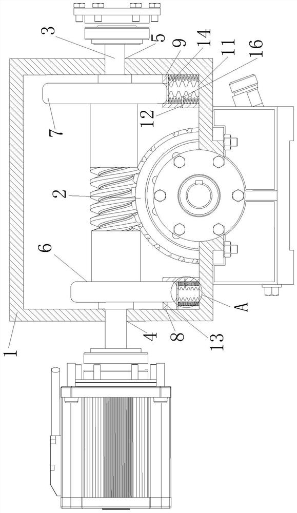
[0034] As a specific embodiment of the present invention, the extrusion assembly includes a No. 1 cam 6 and a No. 2 cam 7; the No. 1 cam 6 and the No. 2 cam 7 are fixedly connected to both sides of the worm 3;

[0035] The worm gear 2 and the worm 3 start to work, and the worm 3 starts to rotate under the drive of the motor, and at the same time drives the No. 1 cam 6 and the No. 2 cam 7 fixedly connected to both sides of the worm 3 to rotate, and the worm 3 transmits the power of the engine to the No. 1 cam 6 and The No. 2 cam 7 makes the No. 1 cam 6 and the No. 2 cam 7 start to work for extruding, thereby extruding the cooling assembly.

[0036] As a specific embodiment of the present invention, the cooling assembly includes No. 1 airbag box 8 and No. 2 airbag box 9; No. 1 airbag 10 and No. 2 airbag box 9 are fixedly installed inside the No. 1 airbag box 8 and No. 2 airbag box 9 No. 1 airbag 11; the No. 1 airbag 10 and the No. 2 airbag 11 are fixedly connected with an air no...

Embodiment approach

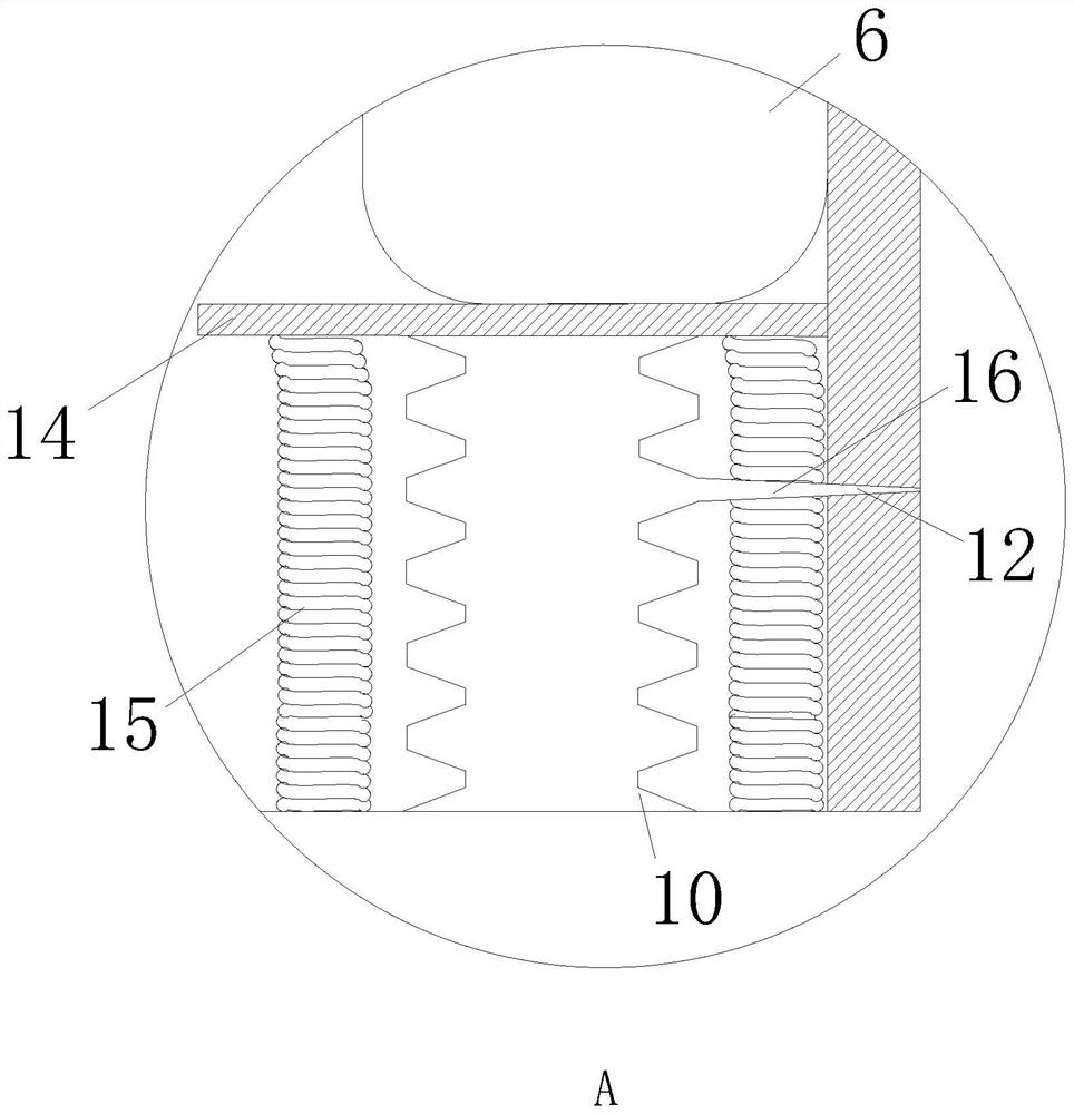
[0044] As a specific embodiment of the present invention, the four corners of the lower end of the baffle plate 14 are respectively fixedly connected with springs 15; the bottom end of the spring 15 is fixedly connected with the support frame 1;

[0045] The spring 15 fixedly connected to the lower end of the baffle plate 14 utilizes the elastic force of the spring 15 to further slow down the impact force of the first cam 6 and the second cam 7 on the first airbag 10 and the second airbag 11, and the spring 15 can be on the first cam 6 at the same time. And the second cam 7 turns away from the No. 1 airbag 10 and the No. 2 airbag 11 and rebounds to help the baffle plate 14 to reset quickly. No. 1 airbag 10 and No. 2 airbag 11 re-inhale the speed, ensure that No. 1 airbag 10 and No. 2 airbag 11 end inhalation before being squeezed next time, thereby guarantee the normal carrying out of airbag blowing heat dissipation work.

[0046] As a specific embodiment of the present invent...


PUM


Abstract

The invention belongs to the technical field of mechanical transmission, and particularly relates to a precise worm and gear. An air bag is additionally arranged in a worm and gear working device, a fixedly-connected cam is driven to rotate through rotation of the worm, the air bag can be periodically extruded through rotation of the cam, the air bag is made to blow air outwards, and airflow flowing is formed in a speed reduction device; therefore, the working worm gear and worm are cooled by air, and the defect that the contact position of the worm gear and worm is easy to damage due to the fact that a large amount of heat is generated when the traditional worm gear and worm work in the speed reducer is overcome, and meanwhile, when the worm gear and worm work, the air bag blows air to the meshing position of the worm gear and worm. And metal scraps generated during friction of the worm gear and the worm can be blown away, the working precision of the worm gear and the worm is guaranteed, and the service life of the worm gear and the worm is effectively prolonged.

Description

technical field [0001] The invention belongs to the technical field of mechanical transmission, in particular to a precision worm gear. Background technique [0002] The precision worm gear structure is often used to transmit motion and power between two interlaced shafts. It is widely used in occasions where the two shafts are interlaced, the transmission ratio is large, the transmission power is not large, or intermittent work is required. It is often used in reduction gears in industrial production. When the gear and worm are used as an important part of the reduction gear, the number of revolutions of the motor can be reduced to the required number of revolutions, and a larger torque can be obtained. [0003] However, when the worm gear is meshed and driven, the relative sliding speed between the meshing gear teeth is large, which will cause serious heat generation on the tooth surface, large friction loss, and metal waste is likely to be generated on the worm gear teeth...

Claims


Application Information

Patent Timeline
Patent Type & Authority Applications(China)
IPC IPC(8): F16H1/16F16H57/04F16H57/023B08B5/02
Inventor 何润东刘茂发
Owner 何润东
Why Eureka
Try Eureka