Flapping wing device for achieving active torsion for flapping wings and wing planes of aerofoil

An airfoil and airfoil technology, which is applied in the field of bionic flapping-wing flight drive devices, can solve the problems such as the inability to simultaneously realize the torsion of the airfoil and the failure of the overall design of the aircraft, and achieve the effects of improving maneuverability, large lift and thrust.

Inactive Publication Date: 2013-08-14
CHANGCHUN INST OF OPTICS FINE MECHANICS & PHYSICS CHINESE ACAD OF SCI
View PDF6 Cites 50 Cited by
  • Summary
  • Abstract
  • Description
  • Claims
  • Application Information

AI Technical Summary

Problems solved by technology

[0004] In order to solve the problem that the existing flapping-wing aircraft drive device can only realize flapping of the wing surface, but cannot realize the twisting of the wing surface at the same time, if it is to be realized at the same time, it is necessary to install additional torsion drive motors for the wings on both sides, which not only increases the mechanical design. Difficulty, will greatly increase the overall weight of the flapping wing device, leading to the technical problem of failure of the overall design of the aircraft, the present invention provides a flapping wing device that realizes wing flapping and wing surface active twisting

Method used


Image

  • Flapping wing device for achieving active torsion for flapping wings and wing planes of aerofoil
  • Flapping wing device for achieving active torsion for flapping wings and wing planes of aerofoil
  • Flapping wing device for achieving active torsion for flapping wings and wing planes of aerofoil

Examples


Embodiment Construction

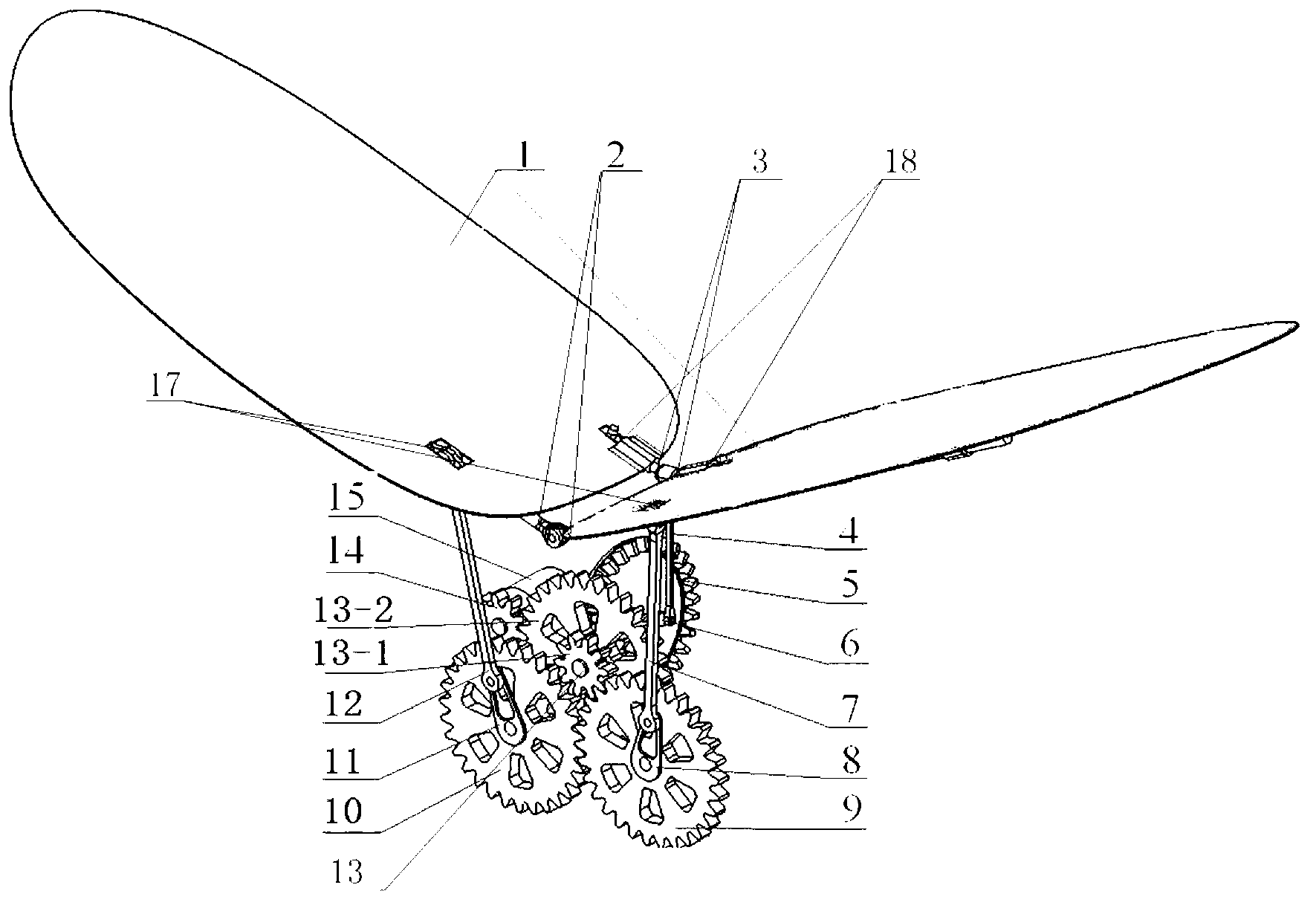
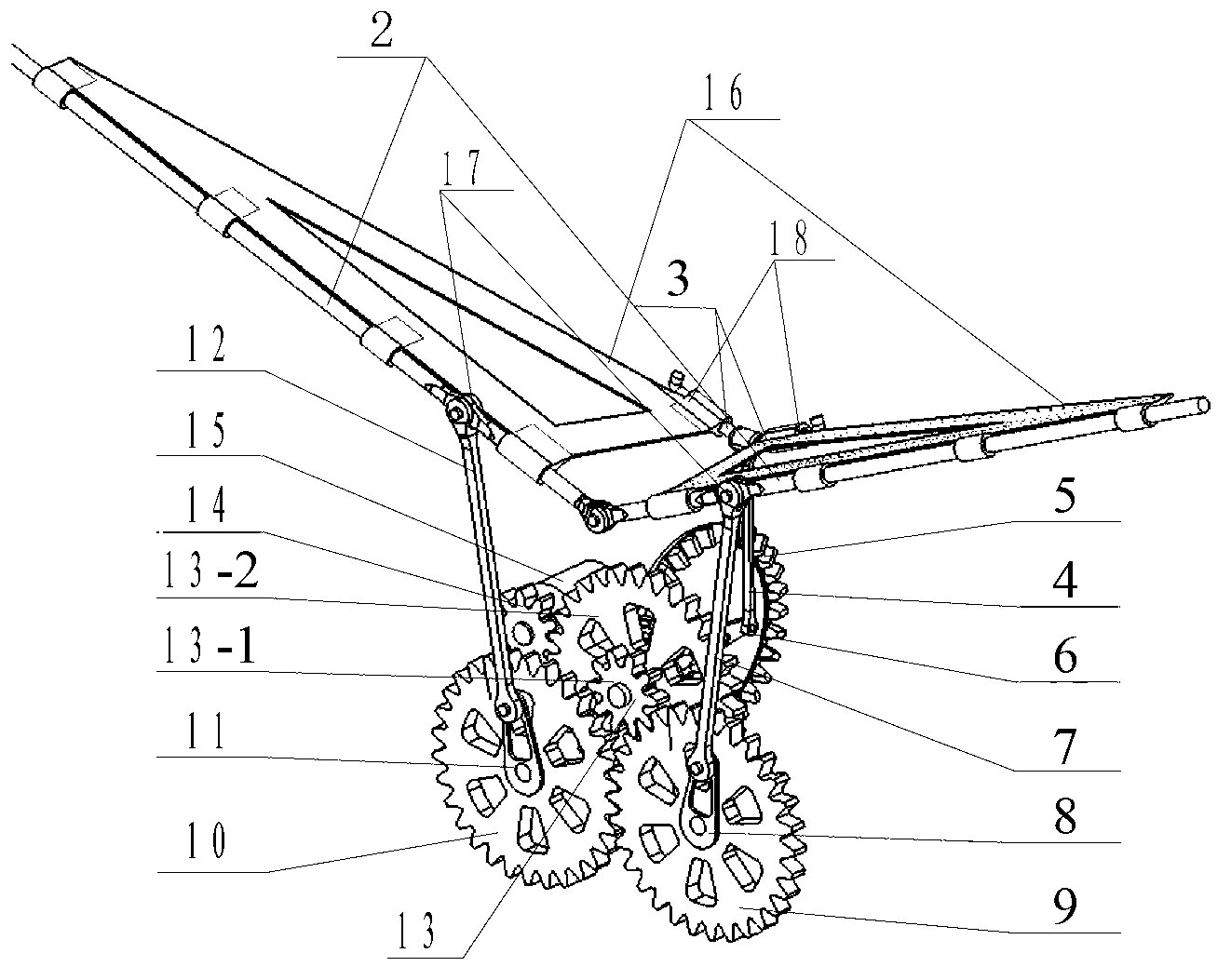
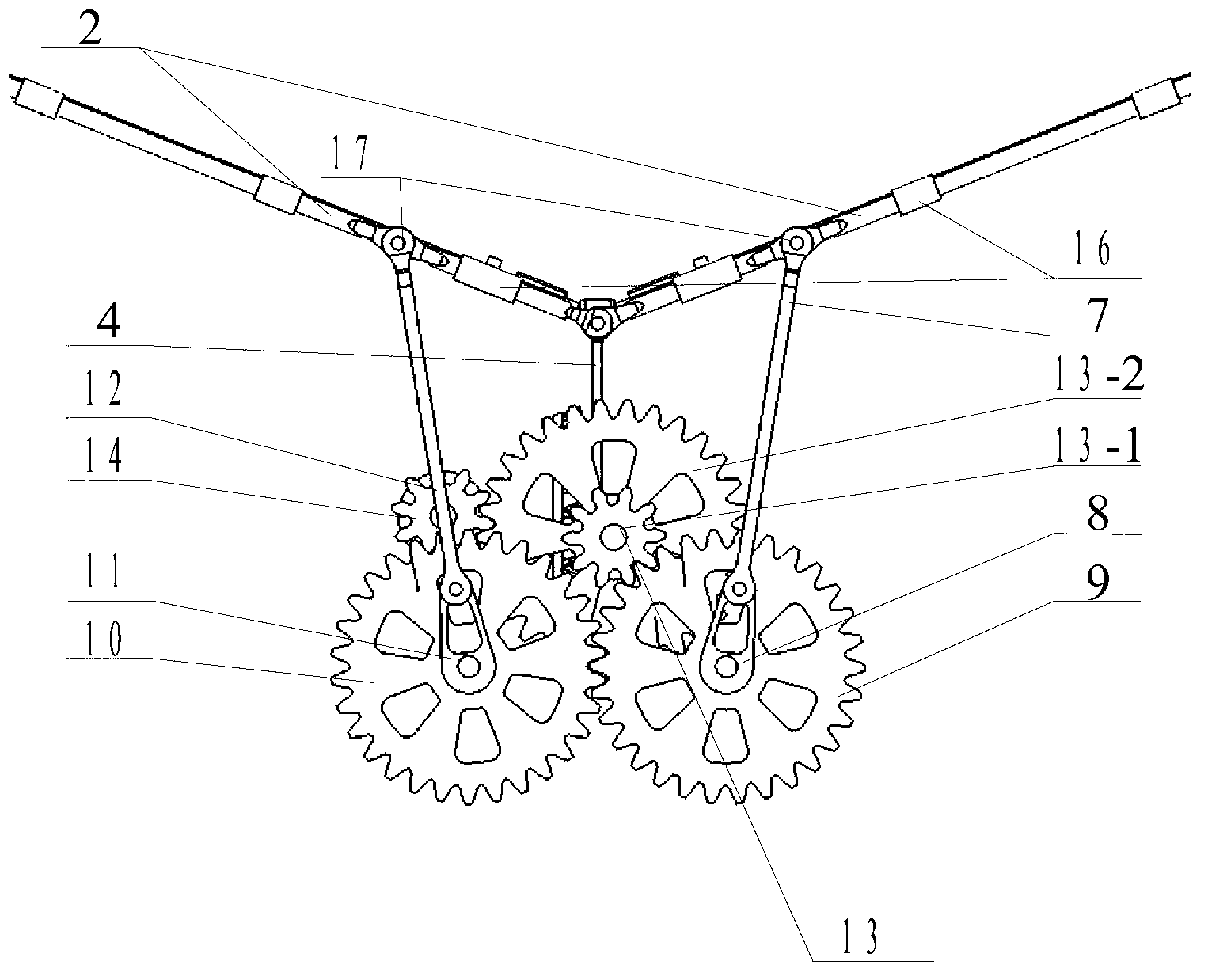
[0018] The present invention will be described in further detail below in conjunction with the accompanying drawings.

[0019] Such as Figure 2 to Figure 6 As shown, the present invention realizes the wing flapping device of the flapping wing and the active twisting of the wing surface comprising: the flapping wing rocker 2, two ball hinge pins 3, the wing torsion connecting rod 4, the driven bevel gear 5, the wing torsion Crank 6, right flapping wing connecting rod 7, right flapping wing crank 8, right flapping wing spur gear 9, left flapping wing spur gear 10, left flapping wing crank 11, left flapping wing connecting rod 12, deceleration Gear 13, motor output gear 14, motor 15, two wing skeletons 16, two rotating pairs 17 and two moving pairs 18. The reduction gear 13 comprises a large spur gear 13-2, a small spur gear 13-1 and a small spur bevel gear 13-3, and the three rotation axes are the same, and the small spur gear 13-1 is fixedly connected to the front end of the ...


PUM


Abstract

The invention discloses a flapping wing device for achieving active torsion of flapping wings and wing planes of an aerofoil, and belongs to the field of bionics flapping wing flight driving devices. The flapping wing device comprises a flapping wing swing rod, two spherical hinge pins, an aerofoil torsion connecting rod, a driven conical gear, an aerofoil torsion crank, a right side flapping wing connecting rod, a right side flapping wing crank, a right side flapping wing straight gear, a left side flapping wing straight gear, a left side flapping wing crank, a left side flapping wing connecting rod, a speed reduction gear, a motor output gear, an electromotor, two aerofoil frameworks, two rotary pairs and two moving pairs. A flapping flight vehicle by adopting the flapping wing device can achieve wing plane flapping and torsion flight of wings at the same time without installing an additional torsion driving motor and a matched drive device thereof for the wings on two sides, and the driving device is integrally simple to design and is light in weight, so that the flapping flight vehicle can obtain great lifting force and push force; and the maneuverability of the flight vehicle is improved to a certain degree.

Description

technical field [0001] The invention belongs to the field of bionic flapping wing flight drive devices, and in particular relates to a flapping wing device for realizing wing flapping and wing surface active twisting. Background technique [0002] The insect flapping-wing aircraft belongs to the bionic flapping-wing aircraft. The flapping wing of insects exists widely in nature, and from an aerodynamic point of view, it can obtain high lift and forward thrust at the same time to realize maneuvering flight. The wing flapping method of insects is specifically periodic flapping around the axis of rotation of the wing root, including flapping around the axis of rotation of the root of the wing and rotation around the axis of rotation in the spanwise direction of flapping, namely: flapping of the wing and twisting of the wing. Wherein the beat forward and downward is called down beat, and the beat backward and upward is called up beat, and each beat cycle is divided into two sta...

Claims


Application Information

Patent Timeline
Patent Type & Authority Applications(China)
IPC IPC(8): B64C33/02
Inventor 孙辉关永亮贾宏光
Owner CHANGCHUN INST OF OPTICS FINE MECHANICS & PHYSICS CHINESE ACAD OF SCI
Why Eureka
Try Eureka