Let-off device of warp knitting machine

A warp knitting machine and warp let-off technology, used in warp knitting, textiles, papermaking, knitting, etc., can solve the problems of product type limitation, inability to meet, and inability to meet different requirements of warp let-off and density, and reduce the flatness The effect of occupying area, making full use of and avoiding yarn breakage

Inactive Publication Date: 2013-08-14
CHANGZHOU WUJIN WUYANG TEXTILE MACHINERY
View PDF11 Cites 14 Cited by
  • Summary
  • Abstract
  • Description
  • Claims
  • Application Information

AI Technical Summary

Problems solved by technology

Such warp beam frames all use electronic let-off, so they cannot meet the different requirements for let-off amount and density when weaving different products, and the product types are limited, especially cannot meet the requirements for weaving double-sided forming jacquard plush fabrics.

Method used


Image

  • Let-off device of warp knitting machine
  • Let-off device of warp knitting machine
  • Let-off device of warp knitting machine

Examples


Embodiment Construction

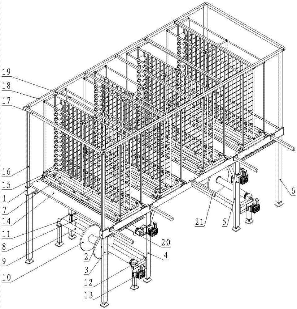
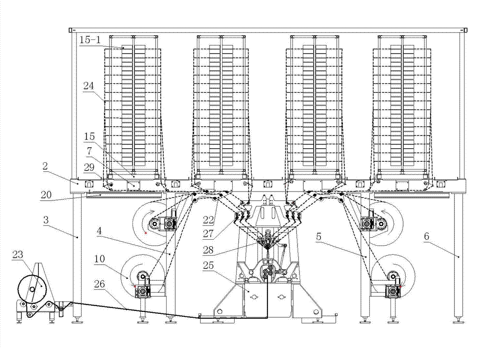
[0014] Such as figure 1 , 2 As shown in and 3, a let-off device of a warp knitting machine includes a creel let-off unit and a creel let-off unit, and the creel let-off unit is located above the creel let-off unit.

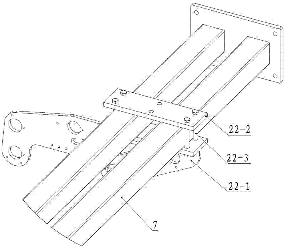
[0015] The beam frame let-off unit comprises a top bracket, a side bracket, a warp beam 9, a warp beam installation assembly and a yarn guide rod assembly 22, the top bracket is supported on the installation surface by the side bracket, and the warp beam 9 is installed on the side by the warp beam installation assembly. On the support, the yarn guide rod assembly 22 is installed on the top support, and the creel let-off unit includes at least one set of creel devices 15, and the creel device 15 is installed on the top support of the warp creel let-off unit, and the creel device 15 The bottom has a yarn dividing device 29, and the pan head 10 on the warp beam 9 sends yarn to the main frame 25 of the warp knitting machine through the yarn guide rod assembly 22, and...


PUM


Abstract

The invention relates to a textile manufacturing machine, in particular to a let-off device of a warp knitting machine. The let-off device comprises a creel let-off unit and a beam creel let-off unit. The creel let-off unit is located above the beam creel let-off unit. A top support of the beam creel let-off unit is supported on a mounting face through side supports. A beam is mounted on the side supports through a beam mounting component. A guide rod component is mounted on the top support. The creel let-off unit comprises at least one creel set mounted on the top support of the beam creel let-off unit. A pan head on the beam and a bobbin on the creel device are let off yarns to the warp knitting machine through the guide rod component. The let-off device has the advantages that the different requirements on let-off amount and tension are met, the whole warp knitting machine is compact in structure, space is fully utilized, plane area is reduced, let-off length is shortened, and yarn breakage caused by the fact that the excessive let-off length makes tension difficult to control is avoided effectively.

Description

technical field [0001] The invention relates to a textile machine, in particular to a let-off device of a warp knitting machine. Background technique [0002] The existing warp beam frame for double-needle bed warp knitting machine includes a plurality of pan head support seats fixedly connected to the lateral sides of the double needle bed warp knitting machine body, and the pan head set on the lateral sides. The supporting base is rotatably connected and arranged in parallel with a plurality of warp beams, a yarn guide rod assembly, a tension adjustment mechanism, and a yarn loop forming mechanism located at the lower part of the tension adjustment mechanism. The rod assembly includes a yarn guide rod base and a yarn guide rod installed thereon, and the tension adjustment mechanism includes a tension rod base, a tension rod and a tension sheet, and the tension adjustment mechanism is fixedly connected with the bed through the tension rod base; , the yarn passes through th...

Claims


Application Information

Patent Timeline
Patent Type & Authority Applications(China)
IPC IPC(8): D04B27/10
Inventor 王敏其王水赵启周旭锋
Owner CHANGZHOU WUJIN WUYANG TEXTILE MACHINERY
Why Eureka
Try Eureka