
Working surface hydraulic support with array proximity sensing devices and linearity control method of hydraulic support

A technology of proximity sensing device and hydraulic support, applied in mine roof support, earth-moving drilling, mining equipment, etc., can solve the straightness deviation of hydraulic support and scraper conveyor, the difficulty of controlling the straightness of hydraulic support, and the normal mining of working face. Work impact and other issues, to achieve the effect of high reliability, simple structure and low cost

Active Publication Date: 2013-08-14
BEIJING TIANMA INTELLIGENT CONTROL TECH CO LTD
View PDF5 Cites 23 Cited by
  • Summary
  • Abstract
  • Description
  • Claims
  • Application Information

AI Technical Summary

Problems solved by technology

However, since there is no mutual constraint between the hydraulic supports on the working face, it is difficult to realize the straightness control of the hydraulic supports
Moreover, in the prior art, the control of straightness basically depends on the travel distance of the stroke sensor to determine, without a set of calibration feedback mechanism, once the stroke sensor fails, the straightness of each hydraulic support and scraper conveyor will be greatly deviated In severe cases, underground accidents will be caused, which will have a serious impact on the normal mining work of the working face.

Method used


Image

  • Working surface hydraulic support with array proximity sensing devices and linearity control method of hydraulic support
  • Working surface hydraulic support with array proximity sensing devices and linearity control method of hydraulic support
  • Working surface hydraulic support with array proximity sensing devices and linearity control method of hydraulic support

Examples


Embodiment Construction

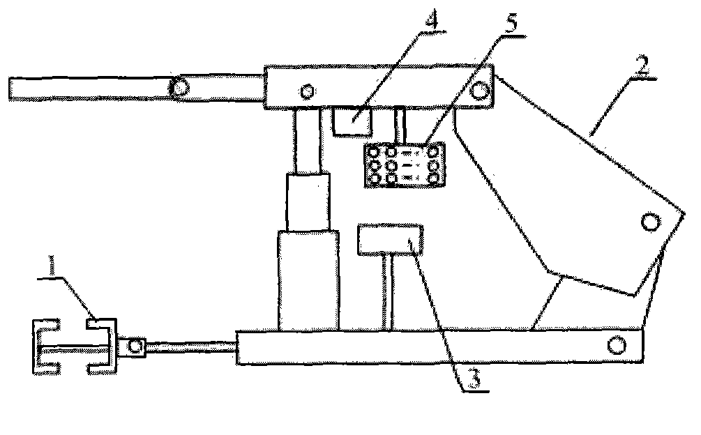
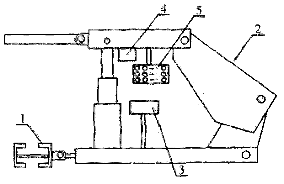
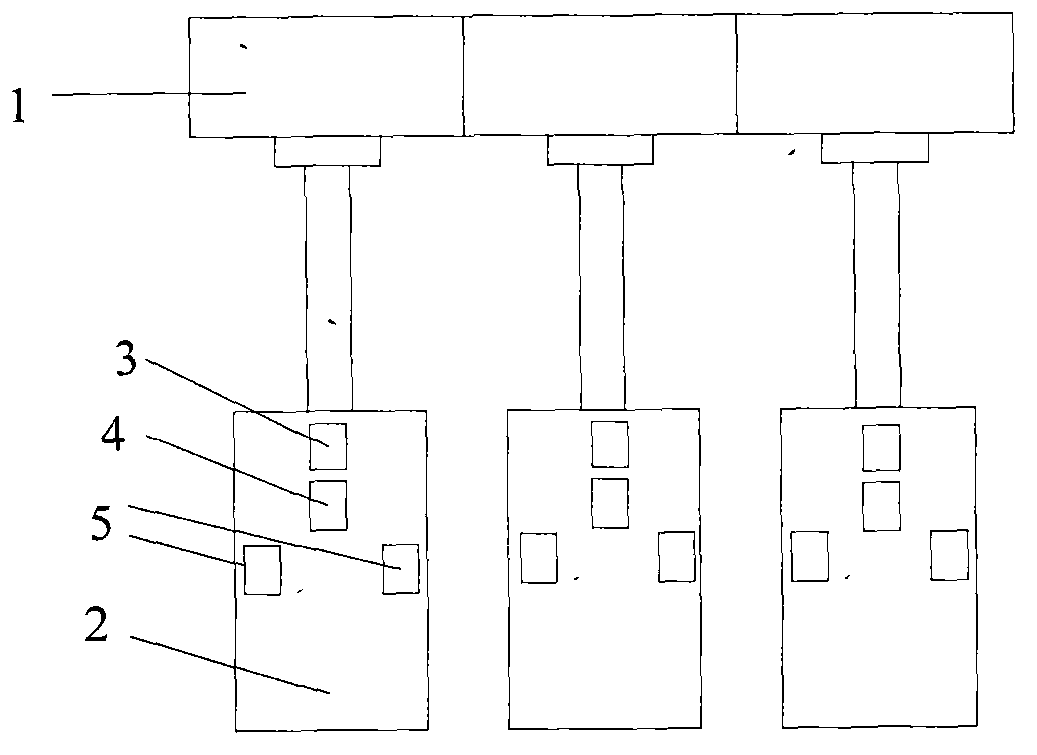
[0026] See attached Figure 1-2 , which describes a preferred embodiment of the working face hydraulic support with an array proximity sensing device according to the present invention. The hydraulic support includes a top beam and a support controller. The support controller can control basic operations such as lowering, moving, and adjusting the inclination of the roof, and can communicate with other support controllers to send and receive data information. One or more inclination sensors are arranged on the top beam to monitor the inclination angle of the top beam. The support controller is electrically connected to the inclination sensors to receive the inclination angle data of the top beam. There is an array proximity sensor on each side of the top beam. The sensing device is preferably installed on the lower part of the top beam by means of suspension, and the two array proximity sensing devices are arranged symmetrically along the length direction of the top beam. The...


PUM


Abstract

A working surface hydraulic support with array proximity sensing devices comprises a top beam and a support controller. A tilt angle sensor is arranged on the top beam, two sides of the top beam are respectively provided with one array proximity sensing device, the two array proximity sensing devices are symmetrically arranged along the length direction of the top beam, and the support controller is electrically connected with the tilt angle sensor and the array proximity sensing devices. The working surface hydraulic support has the advantages that the support moving stroke of the hydraulic support is controlled according to the positional relation between each array proximity sensing device and the adjacent hydraulic support, the moved hydraulic support is controlled as a hydraulic support moving marker post, the working surface hydraulic support is simple in system structure, low in cost, high in reliability, convenient to mount, maintain and use and the like, the support falling height in the support moving process can be effectively controlled, a system is safer, the whole support moving process includes an extensive control stage and a fine control stage, and the control system is high in control efficiency and precision.

Description

technical field [0001] The invention relates to a working face hydraulic support, in particular to a hydraulic support provided with an array type proximity sensing device and a method for controlling the straightness of the support using the hydraulic support. Background technique [0002] The fully mechanized mining face is composed of shearer, scraper conveyor, hydraulic support and other equipment. The scraper conveyor is composed of a section of a chute connected. The connecting hole of the scraper conveyor and the hydraulic support push rod connection head are fixed and connected by pins, and the telescopic action of the jack is pushed through the hydraulic support on the working surface. Realistic scraper conveyor of the mobile. Multiple hydraulic supports are arranged in sequence on the working surface, and their respective positions are constrained by the scraper conveyor on the working surface, but their mutual positions are not constrained, which is a semi-floati...

Claims


Application Information

Patent Timeline
IPC IPC(8): E21D23/16E21D23/12
Inventor 牛剑峰李俊士
Owner BEIJING TIANMA INTELLIGENT CONTROL TECH CO LTD
Features
  • Generate Ideas
  • Intellectual Property
  • Life Sciences
  • Materials
  • Tech Scout
  • Unparalleled Data Quality
  • Higher Quality Content
  • 60% Fewer Hallucinations
Learn More