
Precision forging blade thickness plastic deformation compensation method

A technology of plastic deformation and blade thickness, which is applied to the supporting elements of blades, engine elements, machines/engines, etc., can solve the problems of low work efficiency and long manufacturing cycle of precision forging dies, and achieve shortened manufacturing cycle, increased die life, The effect of reducing the number of repairs

Active Publication Date: 2015-05-27
AECC AVIATION POWER CO LTD
View PDF4 Cites 1 Cited by
  • Summary
  • Abstract
  • Description
  • Claims
  • Application Information

AI Technical Summary

Problems solved by technology

Its disadvantages are: the manufacturing cycle of the precision forging die is long and the work efficiency is low

Method used


Image

  • Precision forging blade thickness plastic deformation compensation method
  • Precision forging blade thickness plastic deformation compensation method

Examples


Embodiment 1

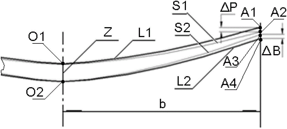
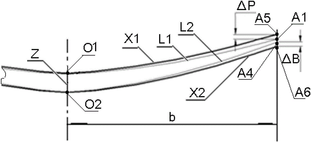
[0020] Example 1, manufacturing a precision forging die for a certain type of aero-engine blade, the half-chord length b of the blade is 14mm, and the initial compensation value ΔP 0 =0.08mm, ΔB 0 =0.1mm, according to the initial compensation amount compensation, the mold is used for trial forging, and the three-coordinate measuring machine is used for detection, ΔP 1 and ΔB 1 If it is less than 0.01mm, use the initial compensation surface as the mold parameter to make the mold.

Embodiment 2

[0021] Example 2, manufacturing a precision forging die for a certain type of aero-engine blade, the half-chord length b of the blade is 31mm, and the initial compensation value ΔP 0 =0.11mm, ΔB 0 =0.14mm, according to the initial compensation amount compensation, the mold is subjected to trial forging, and the three-coordinate measuring machine is used for detection, ΔP 1 =0.04mm and ΔB 1 =0.03mm, then repeat steps 1.2 to 1.4 to get the compensation value ΔP for the next test forging 2 and ΔB 2 If it is less than 0.01mm, use the first compensation surface as the mold parameter to make the mold.

Embodiment 3

[0022] Example 3, manufacturing a precision forging die for a certain type of aero-engine blade, the half-chord length b of the blade is 57mm, and the initial compensation value ΔP 0 =0.16mm, ΔB 0 =0.22mm, according to the initial compensation amount compensation, the mold is used for trial forging, and the three-coordinate measuring machine is used for detection, ΔP 1 = 0.07mm and ΔB 1 = 0.06mm, then repeat the method from step 1.2 to step 1.4 to get the compensation value ΔP for the next trial forging 2 =0.03mm and ΔB 2 =0.03mm, then repeat the method from step 1.2 to step 1.4, ΔP 3 and ΔB 3 If it is less than 0.01mm, use the second compensation surface as the mold parameter to make the mold.


PUM


Abstract

The invention belongs to manufacturing technologies for aviation engine blade precision forging dies and relates to a precision forging blade thickness plastic deformation compensation method. The compensation method is characterized by comprising a step (1.1) of determining maximum compensation values delta P0 and delta B0 according to elastic-plastic deformation characteristics of a blade, a step (1.2) of determining a blade basin compensation molded line X1, a step (1.3) of determining a blade back compensation molded line X2, a step (1.4) of determining first-time trial forging maximum compensation values delta P1 and delta B1, and repeating the step (1.2) to the step (1.4) until two maximum compensation values are no greater than 0.01mm. According to the precision forging blade thickness plastic deformation compensation method, pliers maintenance times of a precision forging die is greatly reduced, a manufacturing cycle of the precision forging die is shortened, and working efficiency is improved.

Description

technical field [0001] The invention belongs to the manufacturing technology of precision forging molds for aeroengine blades, and relates to a method for compensating the plastic deformation of precision forging blade profiles. Background technique [0002] At present, the design of precision forging dies for aero-engine blades is carried out according to the theoretical surface, and the dimension data of each cross-section of the blade precision forging die cavity is designed according to the theoretical profile of the corresponding cross-section of the precision forging blade. Due to the elastic-plastic deformation characteristics of the blade material, the thin-walled structure of the blade itself, and the release of residual stress after heat treatment, the actual profile of the blade precision forged by the die designed according to the theoretical profile will deviate from the theoretical profile, and the precision forging die must be adjusted according to the deviatio...

Claims


Application Information

Patent Timeline
Patent Type & Authority Patents(China)
IPC IPC(8): F01D5/14
Inventor 姚贵张勇王利歌姚文广卜军洁孟庆军
Owner AECC AVIATION POWER CO LTD
Learn More