Multi-electrode spiral feeding integral blade wheel inter-blade passage electrolytic machining method

A technology of integral impeller and screw feeding, applied in the field of electrolytic machining, to achieve the effect of simplifying machine tool structure, improving efficiency and good versatility

Inactive Publication Date: 2009-08-19
NANJING UNIV OF AERONAUTICS & ASTRONAUTICS
View PDF3 Cites 33 Cited by
  • Summary
  • Abstract
  • Description
  • Claims
  • Application Information

AI Technical Summary

Problems solved by technology

These patents propose some processing methods for the flow passages between the blades of the overall impeller, but each of the flow passages between the blades is processed separately in the processing process. Usually, an impeller often has dozens to hundreds of such flow passages, and a single flow passage The efficiency of channel processing is very low. If multiple c

Method used


Image

  • Multi-electrode spiral feeding integral blade wheel inter-blade passage electrolytic machining method
  • Multi-electrode spiral feeding integral blade wheel inter-blade passage electrolytic machining method
  • Multi-electrode spiral feeding integral blade wheel inter-blade passage electrolytic machining method

Examples


Embodiment Construction

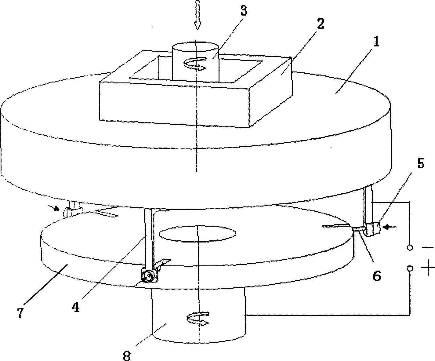
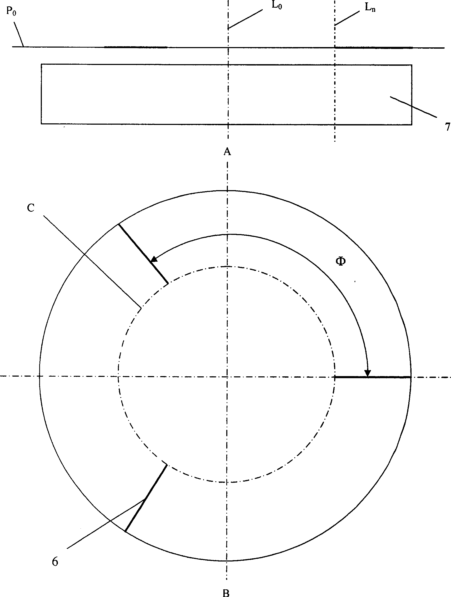
[0028] Such as figure 2 As shown, multiple tool cathodes 6 are distributed on the same horizontal plane P0, and multiple tool cathodes 6 are spaced at an angle Among them, N and M are natural numbers greater than 1, and M is the number of blades of the overall impeller; the ends of a plurality of tool cathodes 6 close to the center of the impeller blank 7 are distributed on the same circle C, and the diameter of the circle C is D=D 0 -2L+2δ, where D 0 is the diameter of the integral impeller 7, L is the length of the integral impeller blade, and δ is the electrolytic machining gap at the end of the cathode; the impeller blank 7 is placed horizontally on the horizontal plane P 0 Below, the impeller blank 7 axis L 0 The extension of the line passes through the center of the circle C.

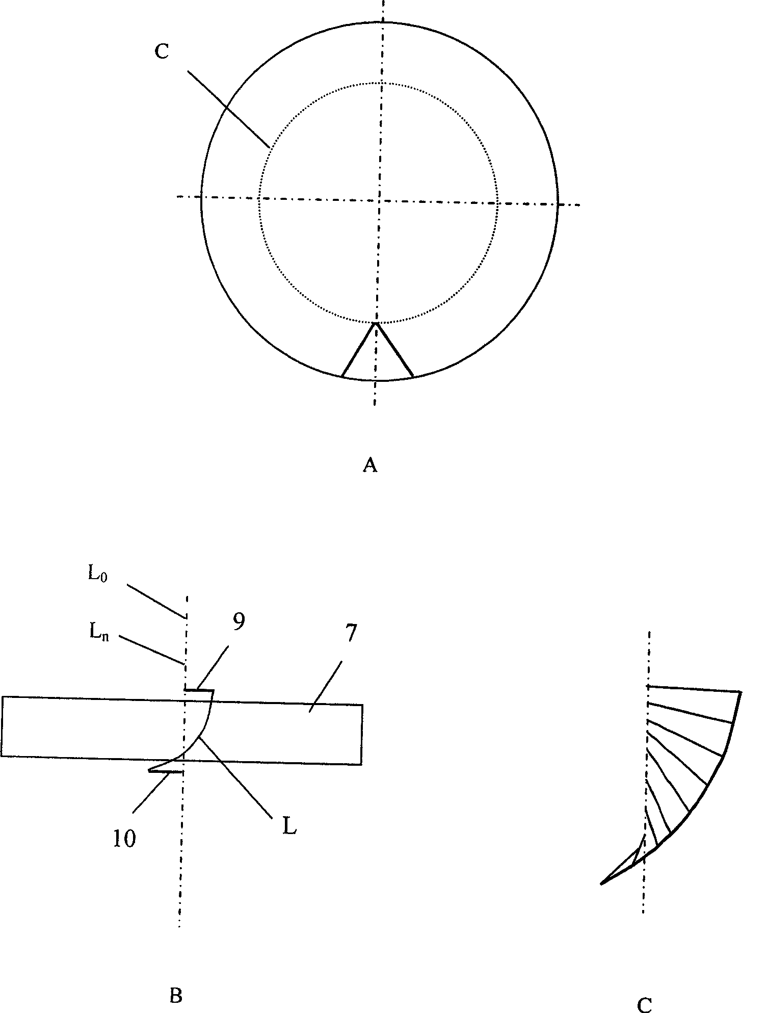
[0029] Such as image 3 As shown, when ready for processing, the tool cathode 6 is located above the overall impeller blank (position 9 in the figure). n Rotate (parallel to the central axi...


PUM


Abstract

The invention relates to an electrolytic machining method for multi-electrode screw feeding integral impeller flow passages, and belongs to the technical field of electrolytic machining. The method adopts a plurality of tool electrodes which are positioned on the same plane and arranged on an electrolytic machining clamp. In the machining process, a translation stage of a machine tool drives the plurality of the tool electrodes to simultaneously feed linearly along the axes direction of an impeller blank, and a turn table on the translation stage drives the plurality of the tool electrodes to rotate; meanwhile, the impeller blank rotates around the axes of the impeller blank, and the tool electrodes perform electrolytic machining along a motion trail determined by the resultant motion. The electrodes and the impeller blank keep a small clearance; electrolyte flows out at a high speed from gaps of the tool electrodes to continuously take away products of electrolysis; and a plurality of impeller flow passages are machined finally. The number and distribution positions of the tool electrodes can be adjusted to meet machining requirements of integral impellers in different types. Because the plurality of the electrodes are adopted to perform machining simultaneously, the machining efficiency for the integral impeller is greatly improved, and the rotation of the electrodes makes machining allowance more even at the same time.

Description

technical field [0001] The invention relates to an electrolytic machining method for a channel between blades of a multi-electrode screw-fed integral impeller, belonging to the technical field of electrolytic machining. Background technique [0002] Electrolytic machining is a special processing technology, which is a processing method that uses the principle of electrochemical anodic dissolution to remove materials. Due to its outstanding advantages, it has been widely used in aerospace, weapons, automobiles, molds and other industries. Especially in the manufacturing technology of the overall impeller of aero-engine, electrolytic machining has become one of the most important processing methods. In recent years, the development of integral impeller materials in the direction of high strength, high hardness, and high toughness, as well as the application of new materials such as titanium alloys and high-temperature heat-resistant alloys, have made the manufacture of integr...

Claims


Application Information

Patent Timeline
IPC IPC(8): B23H9/10
Inventor 朱荻徐庆徐正扬
Owner NANJING UNIV OF AERONAUTICS & ASTRONAUTICS
Why Eureka
Try Eureka