
Sucking disc

A technology of suction cups and discs, which is applied in the direction of suction cups, connecting components, mechanical equipment, etc., and can solve problems such as unavoidable cost savings

Inactive Publication Date: 2013-08-14
FERRO CARBON ENT
View PDF11 Cites 0 Cited by
  • Summary
  • Abstract
  • Description
  • Claims
  • Application Information

AI Technical Summary

Problems solved by technology

[0005] The above-mentioned hook and rod seat can be collectively referred to as the operation part here. If the user needs different types of operation parts to carry objects, he can only purchase the suction cups of various operation parts one by one, so in addition to the problem that the cost cannot be saved , due to the large number of suction cups, there is also the problem of storage; as far as the manufacturer is concerned, according to the functional orientation of different types of operation parts, the suction cups of different types of operation parts must be stocked, so the manufacturer has inventory pressure. Unavoidable increase in inventory costs

Method used


Image

  • Sucking disc
  • Sucking disc
  • Sucking disc

Examples


Embodiment Construction

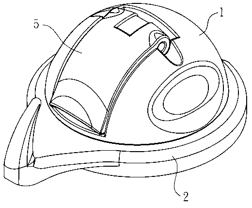
[0030] see Figure 1 to Figure 9 , shown in the figure is the selected embodiment structure of the present invention, which is for illustration only, and is not limited by this structure in the patent application.

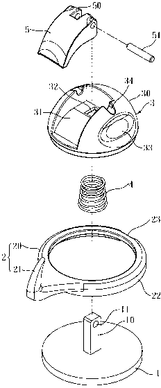
[0031] This embodiment provides a suction cup with improved structure, as shown in Figures 1 to 2, which includes a disc body 1, a socket 2, a fixing seat 3, a spring 4 and a control part 5, wherein:

[0032] Such as figure 2 As shown, the disc body 1 is used to be adsorbed on the wall, and a pull rod 10 is extended from one side of the disc body 1 in the middle, and a shaft hole 11 is set near the end of the pull rod 10 .

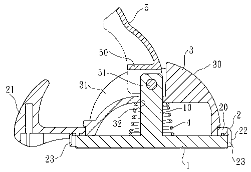
[0033] Figure 2 to image 3 As shown, the sleeve 2 has a ring portion 20, which is attached to the disc body 1 by one side of the pull rod 10, and the sleeve 2 is provided with an operating portion 21 on one side of the ring portion 20. This operation Part 21 takes the hook as an example in this embodiment.

[0034] Figure 2 to image 3 A...


PUM


Abstract

The invention provides a structure improved sucking disc. A disc body is extended to form into a pulling rod; a sleeved connection part is provided with a ring portion and an operating portion; the ring portion is stuck to the disc body; a fixed seat which is in a hemisphere shape is provided with a circular arc surface; a punched hole is formed in a notch which is arranged on the circular arc surface; the fixed seat which is arranged on the ring portion is overlapped on the disc body; the ring portion can rotate between the fixed seat and the disc body in a pivot mode; the pulling rod extends out of the punched hole and a shaft hole is exposed in the notch; a spring is sleeved on the pulling rod and two ends of the spring abut against the disc body and the fixed seat; a control part is provided with a pivot connecting portion which is sleeved on the pulling rod; a rod part is connected with the control part and the pulling rod in a pivot mode; and the control part can correspond to the notch of the fixed seat to be covered to match with the circular arc surface of the fixed seat to form into the sucking disc. The sucking disc has the advantages of enabling users not to need to buy a plurality of sucking discs to be kept to achieve a plurality of pattern transformation of the operating portion and accordingly being capable of reducing the expenses and capable of reducing the inventory for manufacturers due to the fact that the sleeved connection part of the operating portion can change for different patterns for the usage of the suckling disc.

Description

[0001] technical field [0002] The invention relates to a sucker, in particular to a sucker with improved structure. Background technique [0003] Such as Figure 11 As shown, it is a commonly used suction cup, which is used to be adsorbed on the wall and can be used for carrying objects. The structure is mainly composed of a fixed seat 90 and a disc body 91, and a control member 92 is pivotally connected with the pull rod 910 of the disc body 91. , the fixing seat 90 is provided with a hook 900 on the side, when the control member 92 is pulled, the disc body 91 is raised and deformed by the pulling of the pull rod 910, so that a vacuum is formed between the disc body 91 and the attached wall surface, and the fixed The seat 90 can be fixed on the wall, and the bath ball A as shown in the figure can be hung on the hook 900 thereof. [0004] Yet this kind of suction cup can still have the structure of different types except hanging article with aforementioned hook, for examp...

Claims


Application Information

Patent Timeline
IPC IPC(8): F16B47/00
Inventor 陈隆志
Owner FERRO CARBON ENT
Learn More