Wind tunnel test model for aerodynamic braking device

A technology for aerodynamic braking and wind tunnel testing, used in aerodynamic testing, measuring devices, railway vehicle testing, etc.

Inactive Publication Date: 2013-08-14
TONGJI UNIV +1
View PDF6 Cites 8 Cited by
  • Summary
  • Abstract
  • Description
  • Claims
  • Application Information

AI Technical Summary

Problems solved by technology

Numerical simulation and experimental research can be used in the research of aerodynamic braking. With the rapid development of computer technology, the method of computer simulation and numerical analysis has been widely used. However, the accuracy of computer simulation depends on the setting of simulation conditions, network Influenced by various factors such as grid division and fluid simulation method, the accuracy of numerical simulation analysis method needs to be further verified

Method used


Image

  • Wind tunnel test model for aerodynamic braking device
  • Wind tunnel test model for aerodynamic braking device
  • Wind tunnel test model for aerodynamic braking device

Examples


Embodiment Construction

[0022] The present invention will be described in detail below in conjunction with the accompanying drawings and specific embodiments.

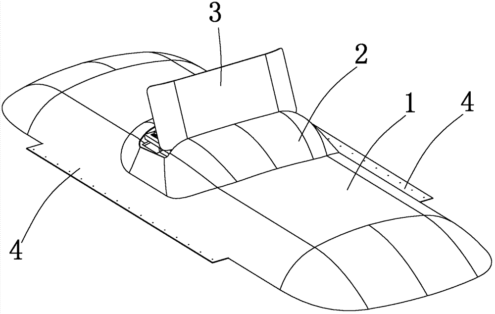
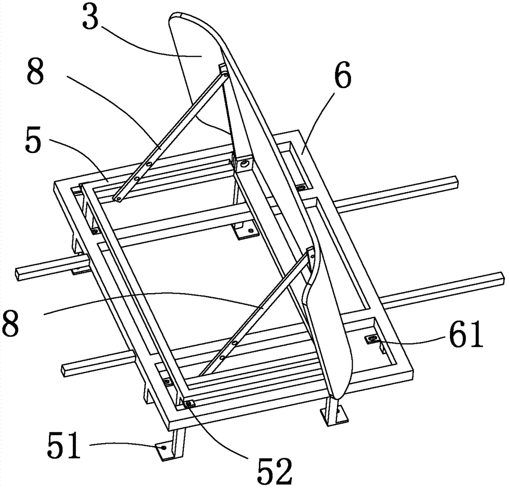
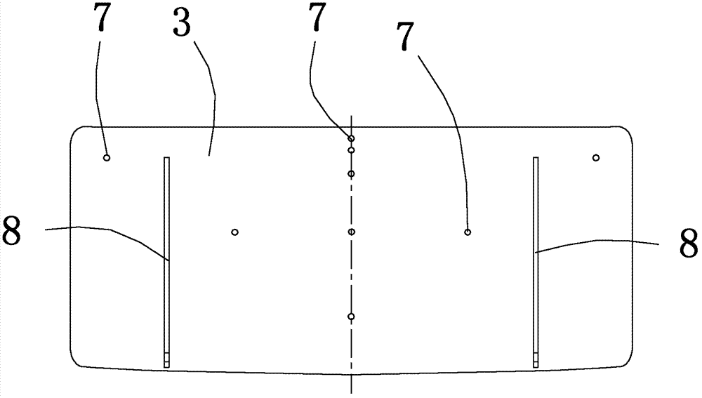
[0023] Example figure 1 , 2 As shown, a wind tunnel test model of an aerodynamic braking device is a hollow structure, including a simulated roof 1, a shroud 2, a brake wind wing 3, an angle adjustment connecting rod 8 and a connecting conversion device 5, simulating The upper surface of the roof 1 has a hole, the position of the air deflector 2 is above the position of the hole on the simulated roof 1, and the edge of the air deflector 2 matches the edge of the hole on the simulated roof 1, and the air deflector 2 2 is streamlined, and the interior of the wind deflector 2 and the interior of the simulated roof 1 form a space. There is a hole in the upper center of the wind deflector 2, and the brake air wing 3 is arranged at the opening position above the wind deflector 2, and is connected with the connection conversion device 5, and the b...


PUM


Abstract

The invention relates to a wind tunnel test model for an aerodynamic braking device, which comprises a simulation car roof, a wind deflector, a braking wind wing, angle adjusting connecting rods and a connection switch device, wherein the wind deflector is arranged above the simulation car roof; the braking wind wing is arranged in the middle of the wind deflector and mounted on the connection switch device; one end of each angle adjusting connecting rod is connected with the connection switch device, and the other end is connected with the braking wind wing; the opening angle of the braking wind wing can be adjusted through the angle adjusting connecting rods; and through the adjustment of the connection switch device, the bearing force and moment of the braking wind wing are measured separately, or the whole bearing force and moment of the braking wind wing and the wind deflector are measured simultaneously. Compared with the prior art, according to the multifunctional aerodynamic braking wind tunnel test model used for aerodynamic braking test research, wind tunnel test verification research can be performed on the aerodynamic force and the fluid field of the aerodynamic braking device from multiple angles, and the wind tunnel test model has the advantages of accuracy in analyzing the aerodynamic braking device, multiple functions and the like.

Description

technical field [0001] The invention relates to a brake device test model for railway vehicles such as magnetic levitation trains, high-speed electric locomotives and high-speed EMUs, in particular to a wind tunnel test model of an aerodynamic brake device. Background technique [0002] Aerodynamic braking is a non-viscous braking method. When the train brakes urgently, the brake air wings above the roof are opened to generate resistance, so that the train stops quickly. The resistance is proportional to the square of the speed, and the speed The higher the value, the greater the braking force. This braking method has excellent performance at high speeds. It makes up for the defects of sticky braking under high-speed braking conditions and ensures safe and reliable braking of high-speed trains. Numerical simulation and experimental research can be used in the research of aerodynamic braking. With the rapid development of computer technology, the method of computer simulation...

Claims


Application Information

Patent Timeline
Patent Type & Authority Applications(China)
IPC IPC(8): G01M9/02G01M9/04G01M17/08
Inventor 田春朱洋永费巍巍李程
Owner TONGJI UNIV
Why Eureka
Try Eureka