Light guide plate

A technology of light guide plate and smooth surface, applied in the field of light guide plate, can solve the problem of poor quality of LED light entrance, and achieve the effect of avoiding the HotSpot phenomenon and increasing the divergence angle.

Active Publication Date: 2013-08-14
东莞恒扬光电有限公司
View PDF9 Cites 5 Cited by
  • Summary
  • Abstract
  • Description
  • Claims
  • Application Information

AI Technical Summary

Problems solved by technology

For the LED light source, since the LED has a limited divergence angle and the energy at the light exit is relatively large, when the light guide plate is lit by the LED, there will be obvious bright and dark phenomena at the light entrance of the light guide plate, that is Commonly known as Hot Spot, so when the light guide plate is covered with glass, it will cause poor quality at the place where the LED enters the light

Method used


Image

  • Light guide plate
  • Light guide plate
  • Light guide plate

Examples


Embodiment Construction

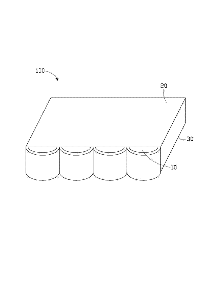
[0012] refer to figure 1 and figure 2 The light guide plate 100 includes a light incident surface 10 , a light exit surface 20 , and a bottom surface 30 opposite to the light exit surface 20 . In this embodiment, the light guide plate 100 is in the shape of a flat plate as a whole, which can be made of acrylic resin, polycarbonate or polyethylene resin and other materials. In other implementation manners, the light guide plate 100 can be set in other shapes as required, such as a wedge shape.

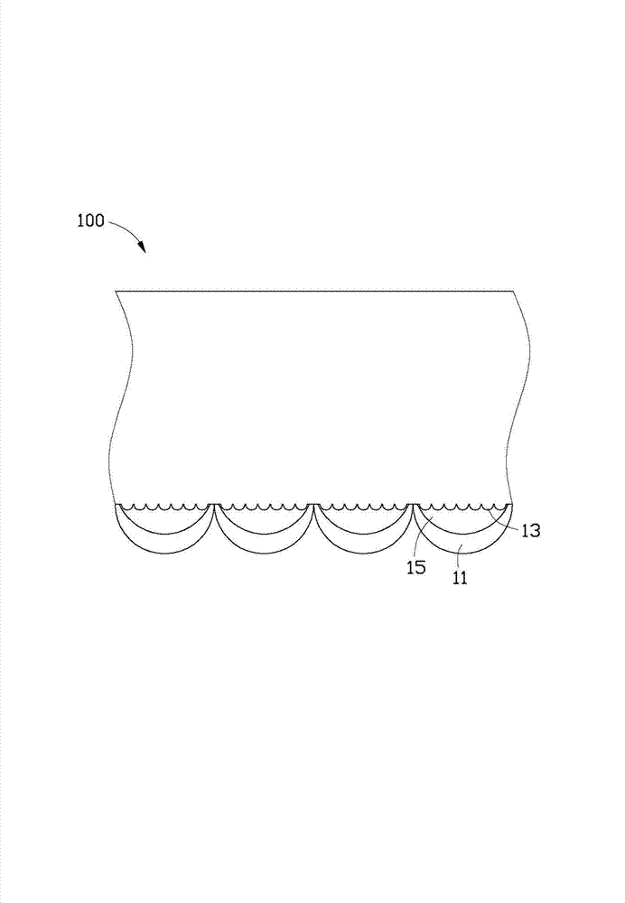
[0013] The light incident surface 10 is provided with a plurality of first microstructures 11 and a plurality of second microstructures 13, the first microstructures 11 are located outside the second microstructures 13, so that the light source needs to pass through the first microstructures 11 Then pass through the second microstructure 13 to enter the light guide plate 100 .

[0014] In this embodiment, the first microstructure 11 has an arc-shaped cross-section, which protrudes f...


PUM


Abstract

The invention provides a light guide plate which comprises a light incident surface, a light emitting surface connected with the light incident surface, and a bottom surface opposite to the light emitting surface, wherein a plurality of first microstructures and second microstructures are arranged on the light incident surface, and the first microstructures are positioned on outer sides of the second microstructures, so that light from the light source penetrates through the first microstructures and the second microstructures and then enters the light guide plate. According to the invention, as the light incident surface of the light guide plate is provided with first microstructures and second microstructures, and light from the light source penetrates through the first microstructures and the second microstructures and then enters the light guide plate, through refraction of the first microstructures 11 and the second microstructures 13, the divergence angle of the LED light source is increased, and energy of the LED light source can be uniformly spread out, so that the Hot Spot phenomenon can be effectively avoided.

Description

technical field [0001] The invention relates to a bracket, in particular to a light guide plate with a microstructure on the light incident surface. Background technique [0002] Liquid crystal display devices have the advantages of lightness, thinness, and low power consumption, and are widely used in modern information equipment. Since the liquid crystal itself in the liquid crystal display panel does not have light-emitting characteristics, in order to achieve the display effect, it is necessary to provide a surface light source device for the liquid crystal display panel, such as a backlight module. light source. For the LED light source, since the LED has a limited divergence angle and the energy at the light exit is relatively large, when the light guide plate is lit by the LED, there will be obvious bright and dark phenomena at the light entrance of the light guide plate, that is It is commonly known as Hot Spot, so when the light guide plate is covered with glass, ...

Claims


Application Information

Patent Timeline
Patent Type & Authority Applications(China)
IPC IPC(8): G02B6/00G02B5/02
Inventor 王何立颖
Owner 东莞恒扬光电有限公司
Why Eureka
Try Eureka