3D display device

A display device and 3D technology, applied in the field of 3D display, can solve the problems of reducing the brightness of the display and affecting the visual experience of the viewer

Active Publication Date: 2013-08-14
BOE TECH GRP CO LTD
View PDF5 Cites 4 Cited by
  • Summary
  • Abstract
  • Description
  • Claims
  • Application Information

AI Technical Summary

Problems solved by technology

[0006] In the 3D display state of the current grating barrier, the shading stripes formed are generally long strips or rectangular shapes. While realizing the 3D display effect, the shading stripes will reduce the brightness of the display due to the shading of light, affecting The viewer's visual experience has also become an obstacle to the promotion and application of naked-eye 3D technology

Method used


Image

  • 3D display device
  • 3D display device
  • 3D display device

Examples


Embodiment Construction

[0020] The specific implementation manners of the 3D display device provided by the embodiments of the present invention will be described in detail below with reference to the accompanying drawings.

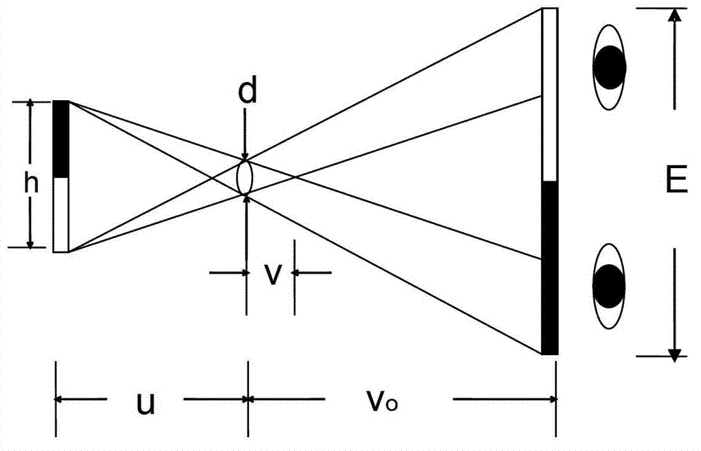
[0021] The 3D display device provided by the example of the present invention utilizes the principle of pinhole imaging, and the conditions for pinhole imaging are briefly described below, as figure 1 As shown, suppose the height of the luminous object is h, the aperture of the grating is d, the distance from the luminous object to the grating is u, and the critical distance of the small hole imaging is v, it can be obtained by the triangular similarity principle: v / d=( v+u) / h, therefore, the critical distance v=ud / (h-d). It can be seen from the formula that when the height h of the luminous object is greater than the aperture d of the grating, the critical distance v is a positive value, and when the height h of the luminous object is smaller than the aperture d of the grating,...


PUM


Abstract

The invention discloses a 3D display device. A first optical grating layer with poriform light-transmitting areas in array arrangement is arranged on the light-emitting side of a display panel; and a second optical grating layer with light-transmitting areas in array arrangement is arranged on the first optical grating layer. by adjusting the sizes of overlapped areas of the light-transmitting areas of the first and second optical grating layers to or not to meet the conditions of pinhole imaging, switch between a 2D display state and a 3D display state is realized; and in the 3D display state, the overlapped area of projections of each pair of poriform light-transmitting areas on the display panel is adjusted to achieve an area with the pin hole imaging condition of being smaller than one pixel unit and realize angle adjustment of emergent light of sub pixel units in the display panel, so that the effect that left eye images and right eye images are collected in different positions is achieved to realize naked-eye 3D display. Therefore, compared with shielding stripes, the 3D display device reduced shielding of light, avoids reducing display brightness and realizes high-brightness 3D display.

Description

technical field [0001] The present invention relates to the technical field of 3D display, in particular to a 3D display device. Background technique [0002] In daily life, people use two eyes to observe the external scene with a three-dimensional sense of space. Three-dimensional (3D) display technology uses the principle of binocular stereo vision to enable people to obtain a sense of three-dimensional space. The main principle is to make the viewer's The left eye and the right eye receive different images respectively, and the position difference caused by the interpupillary distance between the viewer's two eyes makes the two images with "binocular parallax" constitute a "stereoscopic image pair", while the "stereoscopic image "Right" makes the viewer feel three-dimensional after being analyzed and fused by the brain. [0003] Currently, there are two types of 3D display technologies: glasses-free and glasses-based. The so-called naked-eye type is to send encoded 3D v...

Claims


Application Information

Patent Timeline
Patent Type & Authority Applications(China)
IPC IPC(8): G02B27/22G02B26/08G02B30/30
CPCG02B26/08G02B2207/123H04N13/324H04N13/356H04N13/31G02B30/30G02B30/27G02B27/0093
Inventor 武乃福
Owner BOE TECH GRP CO LTD
Why Eureka
Try Eureka