Electronic viewfinder

A viewing window, electronic technology, applied in the field of electronic viewing windows, can solve the problems of inconvenience, general products do not have suitable structure, etc.

Active Publication Date: 2013-08-14
ABILITY ENTERPRISE CO LTD
View PDF5 Cites 0 Cited by
  • Summary
  • Abstract
  • Description
  • Claims
  • Application Information

AI Technical Summary

Problems solved by technology

[0005] This shows that the above-mentioned existing electronic view window obviously still has inconvenience and defects in structure and use, and needs to be further improved urgently.
In order to solve the above-mentioned problems, the relevant manufacturers have tried their best to find a solution, but for a long time no suitable design has been developed, and the general product has no suitable structure to solve the above-mentioned problems. This is obviously the relevant industry. Urgent problem

Method used


Image

  • Electronic viewfinder
  • Electronic viewfinder
  • Electronic viewfinder

Examples


example

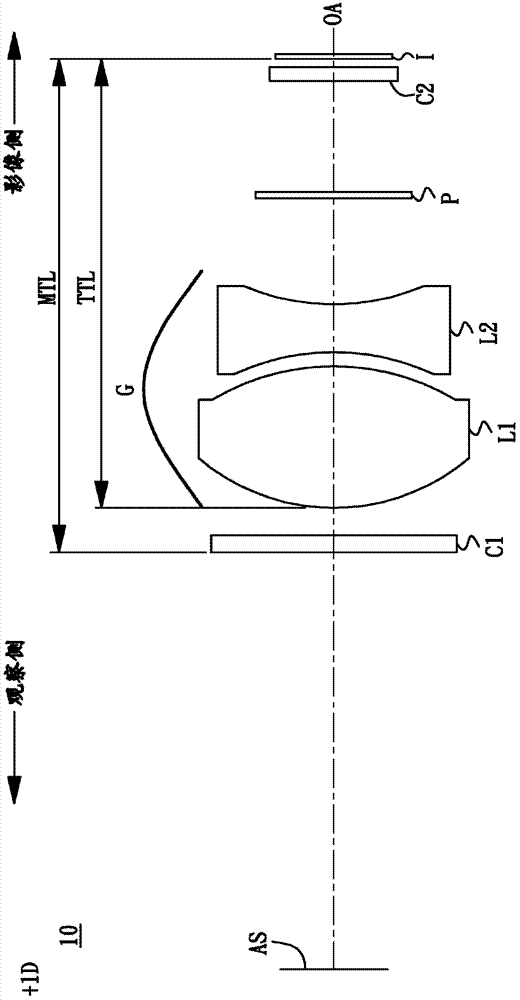
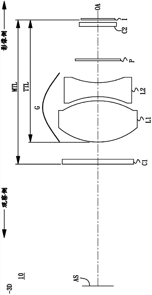
[0054] Table 1 lists the detailed information of an electronic viewing window according to an example of the present invention, which includes the radius of curvature, thickness, refractive index, Abbe number, focal length (effective focal length) of each lens, and the like. The surface codes of the lenses are arranged sequentially from the observation side to the image side, for example: "S1" represents the aperture stop S, "S2" represents the surface of the first plane lens C1 facing the observation side, and "S3" represents the first plane lens The surface of C1 facing the image side, "S4" represents the surface of the first lens L1 facing the viewing side, and so on. In addition, the surface "OBJ" is a virtual surface, and its thickness is defined as the distance between the virtual surface OBJ and the aperture stop S (that is, the pupil of the observer). If the thickness is negative, it means that the surface of OBJ is in front of the pupil. If the thickness is A positive...


PUM

PropertyMeasurementUnit
pore sizeaaaaaaaaaa

Abstract

The invention relates to an electronic viewfinder which sequentially comprises an aperture stop, a lens group and a display device from an observation side to an image side. The electronic viewfinder is characterized in that requirements such as high amplification factor, high definition and observation comfort can be achieved under the conditions of miniaturization and low cost.

Description

technical field [0001] The invention relates to an electronic viewing window, in particular to a light and thin viewing window with low cost, high magnification, high definition and comfortable use. Background technique [0002] An image capturing device, such as a digital video camera or a still camera, captures an image of an object to be photographed by means of a zoom lens and an image sensor. In some image capture devices, the user can also observe the object to be photographed through an electronic viewfinder. The electronic viewing window has a liquid crystal display panel and a lens module. The liquid crystal display panel displays the image captured by the image sensor, and the lens module enlarges the displayed image. [0003] The distance required to observe objects is different for each person, some are shorter and some are longer. Under normal circumstances, the distance L for human eyes to observe an object is between 250 mm and 1000 mm. If the diopter (or ...

Claims


Application Information

Patent Timeline
Patent Type & Authority Applications(China)
IPC IPC(8): G03B13/02G02B13/00G02B13/18G02B1/04
Inventor 许哲源
Owner ABILITY ENTERPRISE CO LTD
Why Eureka
Try Eureka