Power distribution cabinet for power transmission

A technology for power transmission and power distribution cabinets, which is applied in substation/power distribution device housings, electrical components, substation/switch layout details, etc., and can solve problems such as unfavorable power distribution cabinets, burnout of electronic components, and inconvenience to operators

Active Publication Date: 2022-04-12
江苏和谐新能源科技有限公司
View PDF9 Cites 0 Cited by
  • Summary
  • Abstract
  • Description
  • Claims
  • Application Information

AI Technical Summary

Problems solved by technology

[0003] However, when installing the existing outdoor power distribution cabinets, in order to prevent the direct contact between the power distribution cabinets and the ground, the operator usually installs cement blocks to install the power distribution cabinets. This method is easy to consume cement resources and cost less. It is convenient for the operator to move the power distribution cabinet, which is not conducive to improving the use effect of the power distribution cabinet. In addition, the power distribution cabinet will generate a lot of heat when it is in use. Generally, heat dissipation is carried out by setting a cooling net. When there is a lot of dust attached to the cooling net It is not conducive to improving the heat dissipation effect of the power distribution cabinet, and the general heat dissipation net is not easy to disassemble and clean, so it is easy to cause electronic components to burn out when the heat in the power distribution cabinet is high.

Method used


Image

  • Power distribution cabinet for power transmission
  • Power distribution cabinet for power transmission
  • Power distribution cabinet for power transmission

Examples


Embodiment Construction

[0026] In order to make the techniques of the present invention, the creation characteristics, the purpose and efficacy are readily understood, and the present invention is further illustrated in connection with the specific embodiments.

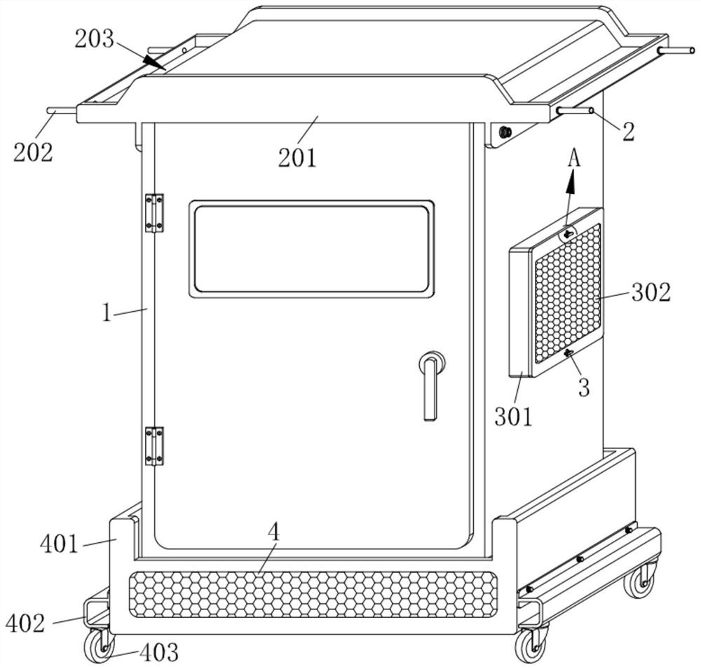
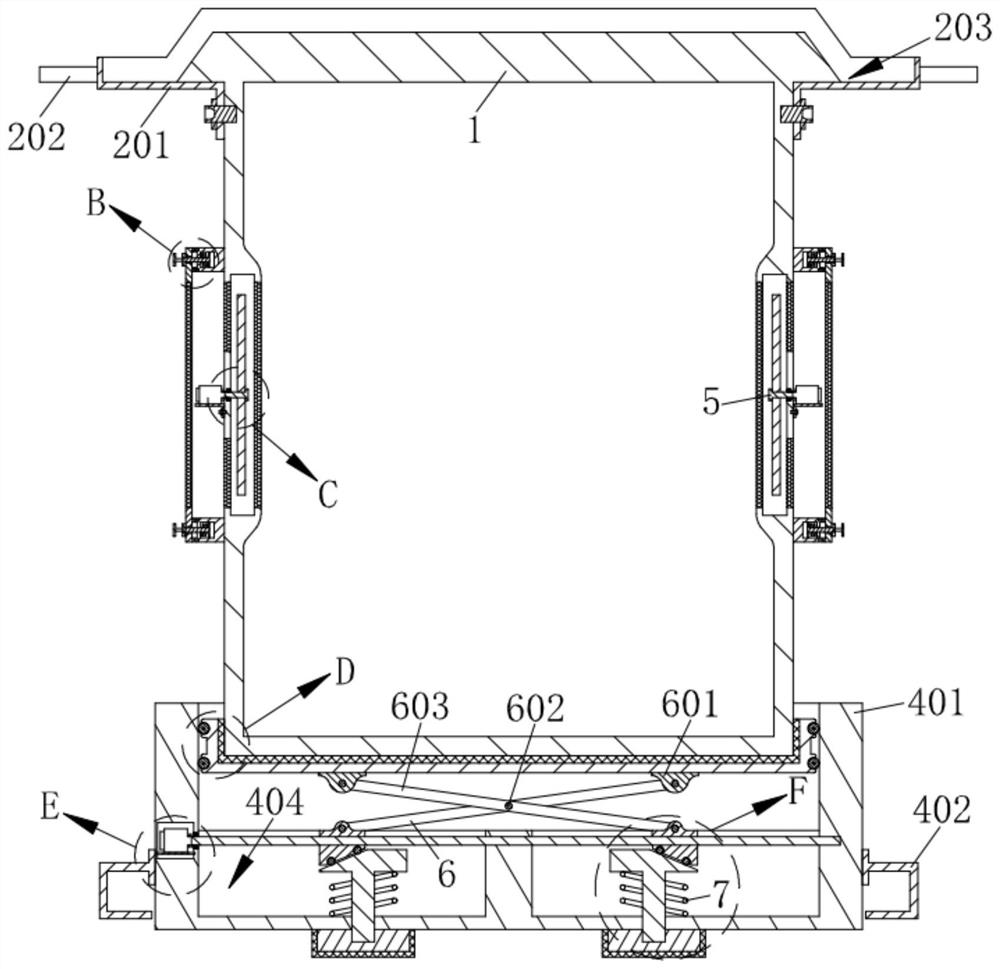
[0027] Such as Figure 1 - Figure 8 As shown, a power conveying cabinet of the present invention includes a cabinet 1, and a fixing mechanism 2 is mounted on the cabinet 1; the cabinet 1 is rotated with a heat dissipation mechanism 5; the cabinet The body 1 is fixed to a dust collecting mechanism 3; a support mechanism 4 is attached to the support mechanism 4; the support mechanism 4 is connected to the sliding mechanism 6 against the finite mechanism 7;

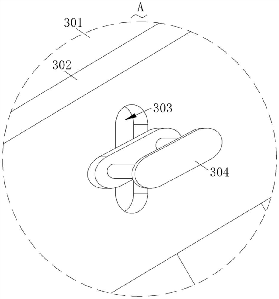
[0028] The dustproof mechanism 3 includes a fixing plate 301 that is fixed to the fixing plate 301, and the fastening plate 301 is engaged with a dustproof mesh 302, and a card slot is provided on the dust-proof mesh 302. 303. The card slot 303 is fitted with a slider 305, and the slider 305 is...


PUM


Abstract

The invention relates to the technical field of power distribution cabinets, in particular to a power distribution cabinet for power transmission, which comprises a cabinet body, and a fixing mechanism is mounted on the cabinet body in a matched manner; a heat dissipation mechanism is rotationally arranged on the cabinet body; a dustproof mechanism is fixed on the cabinet body; a supporting mechanism is mounted on the cabinet body; the supporting mechanism is connected with a sliding mechanism; a limiting mechanism abuts against the sliding mechanism. A control switch of the supporting mechanism is turned on, so that the sliding mechanism drives the cabinet body to slide in the supporting mechanism, and the limiting mechanism is in contact with the ground when being propped by the sliding mechanism, so that the supporting mechanism is conveniently limited while the contact distance between the cabinet body and the ground becomes far; the heat dissipation mechanism is opened, so that heat dissipation is facilitated; an operator rotates the dustproof mechanism with hands, so that the dustproof mechanism is convenient to disassemble and clean, and the situation that the heat dissipation effect in the cabinet body becomes poor due to the fact that much dust is attached to the dustproof mechanism, and electronic elements in the cabinet body are burnt out is prevented.

Description

Technical field [0001] The present invention relates to the field of distribution cabinets, and in particular, a power distribution cabinet for power delivery. Background technique [0002] Distribution cabinet (box) sub-power distribution cabinet (box) and lighting power distribution cabinet (box), meter (box), is the final device of the distribution system. The power distribution cabinet is the collective of the motor control center. The power distribution cabinet is used in the case where the load is divided, and the circuit is small; the motor control center is used in the load concentration, and there are many loops. They allocate electrical energy of a circuit of the previous level distribution device to the close load. [0003] However, existing outdoor power distribution cabinets are installed, in order to prevent direct contact with the ground, it is easy to make the internal moisture, generally set the cement block to reset the power distribution cabinet, which is not e...

Claims


Application Information

Patent Timeline
Patent Type & Authority Applications(China)
IPC IPC(8): H02B1/56H02B1/28H02B1/52H02B1/54H02B1/30
CPCY02A30/14
Inventor 杜全吉宋振胜韩梅芹卞登树
Owner 江苏和谐新能源科技有限公司
Why Eureka
Try Eureka