Method and system universal for power on and power off of various modules
What is AI technical title?
AI technical title is built by PatSnap AI team. It summarizes the technical point description of the patent document.
An electrical module and level technology, applied in the field of communication, can solve problems such as damage to the life of the module, save manpower and material costs, and solve the effect of data loss
Active Publication Date: 2013-08-14
SHENZHEN HONGDIAN TECH CORP
View PDF3 Cites 3 Cited by
Summary
Abstract
Description
Claims
Application Information
AI Technical Summary
This helps you quickly interpret patents by identifying the three key elements:
Problems solved by technology
Method used
Benefits of technology
Problems solved by technology
[0004] The purpose of the embodiment of the present invention is to provide a method and system for powering on and off of various modules. The present invention is to solve the problem that the programmer spends a lot of time debugging the power-on and power-off signal pin of the module. The problem of data loss and damage to the life of the module can save programmers a lot of time, reduce labor costs, and ensure data security and the life of the module.
Method used
Image
Click on the blue label to locate the original text in one second.
Reading with bidirectional positioning of images and text.
Examples
Embodiment 1
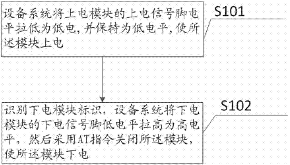
[0022] figure 1 , which shows a flowchart of a method for powering on and off of various modules provided by Embodiment 1 of the present invention. The specific steps of the method are as follows:
[0023] Step S101 , the equipment system pulls down the level of the power-on signal pin of the power-on module to a low level, and keeps it at a low level, so as to power on the module.
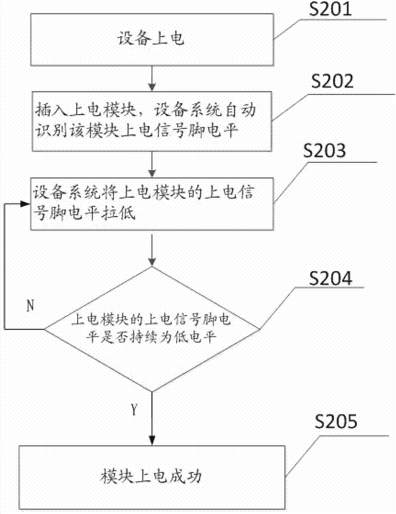
[0024] figure 2 , shows the flow chart of the module power-on method in Embodiment 1 of the present invention, and the specific steps are as follows:
[0025] Step S201, power on the device;
[0026] Step S202, inserting the power-on module, and the equipment system automatically recognizes the level of the power-on signal pin of the module;
[0027] Step S203, the device system pulls down the level of the power-on signal pin of the power-on module;
[0028] Step S204, judging whether the power-on signal pin level of the power-on module is continuously low, if it is continuously low, then exe...
Embodiment 2
[0044] Figure 4 , shows a schematic structural diagram of a system generally used for powering on and off various modules provided by Embodiment 2 of the present invention, and the system includes: a power-on unit 41 and a power-off unit 42 .
[0045] The power-on unit 41 is used for the device system to pull down the power-on signal pin level of the power-on module to a low level and keep it at a low level, so that the module is powered on successfully.
[0046] The power-off unit 42 is used for the equipment system to pull the power-off signal pin of the power-off module to a low level, and then use AT related commands to shut down the module, so that the module is powered off successfully.
[0047] The power-on unit 41 further includes: a level-lowering unit 411 and a judging unit 412 .
[0048] The level-lowering unit 411 is used for the equipment system to lower the level of the power-on signal pin of the power-on module.
[0049] The judging unit 412 is used to judge ...
PUM
Abstract
The invention belongs to the communication field and the circuit control field and particularly relates to a method and a system universal for power on and power off of various modules. The method includes: by an equipment system, lowering a power on signal pin level of a power on module into a low level, and keeping the low level to allow for power on of the module; and recognizing a power off module label, by the equipment system, raising a power off signal pin low level of a power off module into a high level, and using an AT instruction to shut the power off module to allow for power off of the same. By the method, the problems that programmers needs a large amount of time to debug duration of module power on and power off signal pin low levels and abnormal power off causes module data loss and damages the service lives of modules, a large amount time of programmers is saved, labor cost is reduced, and data safety and module service lives are guaranteed.
Description
technical field [0001] The invention belongs to the field of communication and circuit control, and in particular relates to a method and system for powering on and off of various modules. Background technique [0002] As the communication technology becomes more and more advanced, in order to meet the needs of various customers, there are more and more types of modules used. The ability of communication equipment to be compatible with various modules has become a problem faced by various companies. Usually a communication device needs to support a variety of modules, and there are differences between different modules of different manufacturers. Usually, when the device module is powered on, the signal pin needs to have a low level for a certain period of time to power on the module, and it needs to be low for a certain period of time when the module is powered off. To power off the module normally, it also requires a lot of work to debug the low level of power on and off o...
Claims
Application Information
Patent Timeline
Application Date:The date an application was filed.
Publication Date:The date a patent or application was officially published.
First Publication Date:The earliest publication date of a patent with the same application number.
Issue Date:Publication date of the patent grant document.
PCT Entry Date:The Entry date of PCT National Phase.
Estimated Expiry Date:The statutory expiry date of a patent right according to the Patent Law, and it is the longest term of protection that the patent right can achieve without the termination of the patent right due to other reasons(Term extension factor has been taken into account ).
Invalid Date:Actual expiry date is based on effective date or publication date of legal transaction data of invalid patent.

