Eureka AIR delivers breakthrough ideas for toughest innovation challenges, trusted by R&D personnel around the world.

Special transmission device with flexible shock absorption structure for magnetic latching relay

A technology of magnetic latching relay and transmission device, applied in the direction of non-pole relay, etc., to achieve the effect of improving effective driving force, maintaining long-term working stability and reducing loss

Active Publication Date: 2013-08-14
ANHUI YONG AN ELECTRONICS TECH CO LTD
View PDF7 Cites 4 Cited by
  • Summary
  • Abstract
  • Description
  • Claims
  • Application Information

AI Technical Summary

Problems solved by technology

[0004] The technical problem to be solved by the present invention is to solve the deficiencies in the flexible transmission design of the existing magnetic latching relay, and provide a magnetic latching relay transmission device with reliable quality and stable operation

Method used


Image

  • Special transmission device with flexible shock absorption structure for magnetic latching relay
  • Special transmission device with flexible shock absorption structure for magnetic latching relay

Examples


Embodiment 1

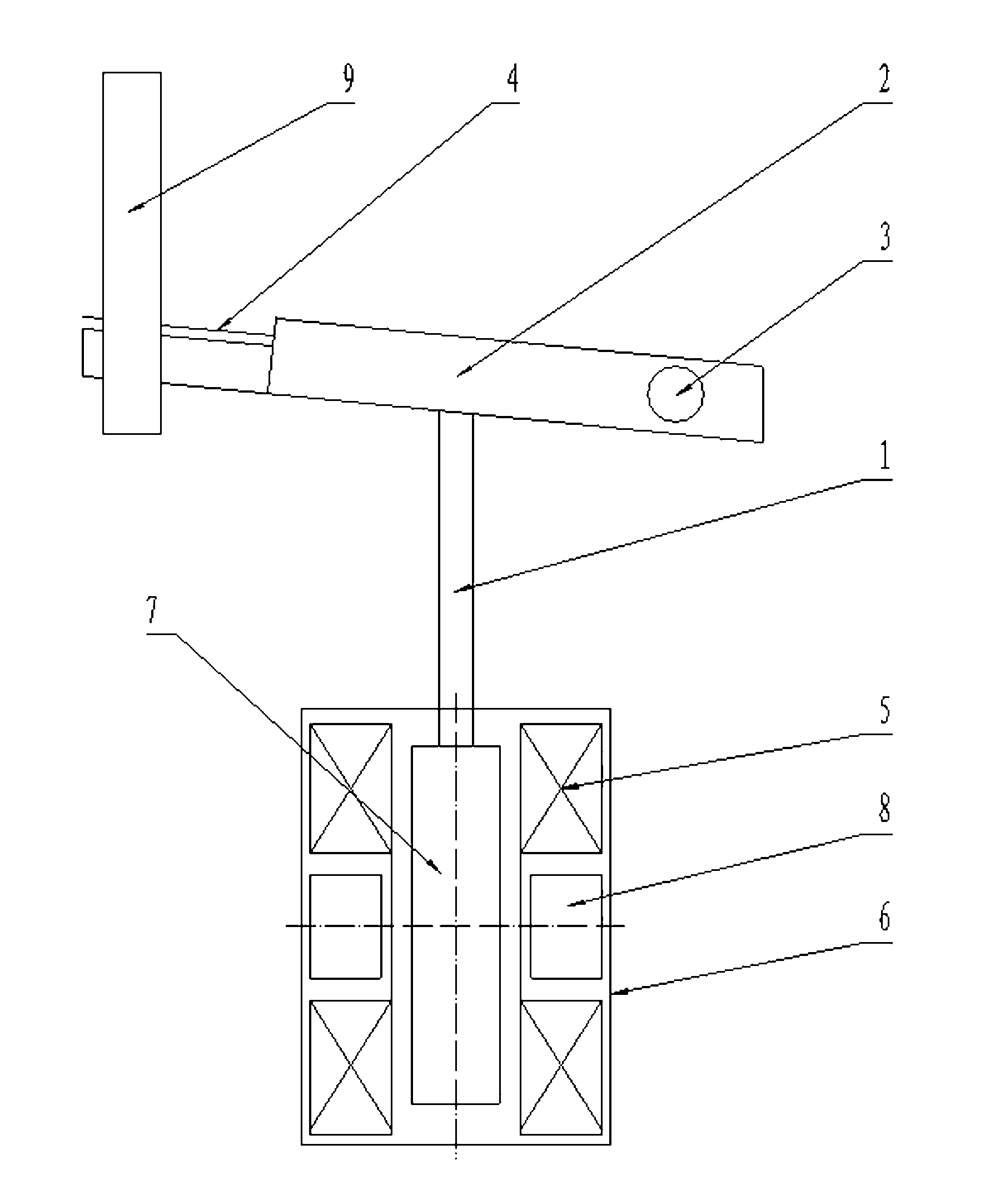
[0021] Such as figure 1 It can be seen that the transmission device with a flexible damping structure for magnetic latching relays of the present invention includes an insulating transmission rod 1, and one end of the insulating transmission rod 1 is provided with a rocker arm 2, and the other end is connected with a magnetic drive device; one end of the rocker arm 2 is provided with a rotating shaft 3. The other end is provided with an overtravel piece 4, and the overtravel piece 4 is arranged above the rocker arm 2 in parallel, and there is a stroke space between the end of the overtravel piece 4 and the end of the rocker arm 2 that can make the overtravel piece 4 yield, so that the overtravel piece 4 The process sheet 4 can play the role of flexible shock absorption.

[0022] When working, the position of the rotating shaft 3 is fixed, and the insulating transmission rod 1 is pushed to be displaced by the magnetic driving device, thereby causing the rocker arm 2 to rotate a...

Embodiment 2

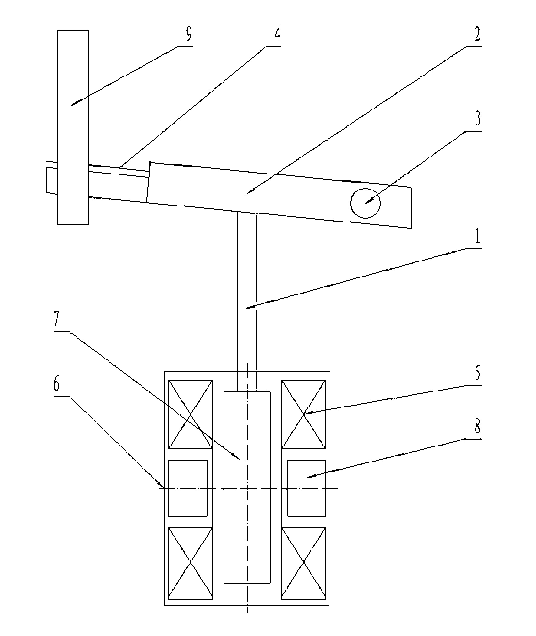
[0028] Such as figure 2 It can be seen that the difference between this embodiment and Embodiment 1 is that in the magnetic drive device, the static iron core 6 is a half-wrapped structure, that is to say, one side of the static iron core 6 is provided with an opening to facilitate the installation of other components. Wind the electromagnetic coil on the coil frame 5, connect the insulating transmission rod 1 to the upper end of the moving iron core 7, install the permanent magnet 8 into one side of the coil frame 5, and then attach the corresponding static iron core 6 to the other magnetic pole of the permanent magnet 8 It is fixed on the end faces of both ends of the coil frame 5 . With this structure, the purpose of transmission and shock absorption can also be achieved, and at the same time, it still has the characteristics of preventing external magnetic field interference.

[0029] The transmission device with a flexible damping structure dedicated to the magnetic lat...


PUM


Abstract

The invention discloses a special transmission device with a flexible shock absorption structure for a magnetic latching relay, of which the quality is reliable and the work is stable. The transmission device comprises an insulation transmission rod, wherein one end of the insulation transmission rod is provided with a rocker arm, and the other end of the insulation transmission rod is connected with a magnetic driving device; one end of the rocker arm is provided with a rotating shaft, and the other end of the rocker arm is provided with an over travel piece; the magnetic driving device comprises coil racks rolled with electromagnetic coils, a static iron core and a movable iron core which can enable the insulation transmission rod to move along the axial direction of the magnetic driving device; the movable iron core is fixedly connected with the insulation transmission rod; the magnetic diving device also comprises a permanent magnet; and one magnetic pole of the permanent magnet is mounted through matching with the static iron core, and the other magnetic pole of the permanent magnet is mounted through matching with the movable iron core.

Description

technical field [0001] The invention relates to a magnetic latching relay for an electric meter, in particular to a special transmission device for the magnetic latching relay. Background technique [0002] There are many defects in the transmission system scheme of the existing magnetic latching relay: 1. The flexible shock absorbing structure (overtravel sheet) is in direct contact with the contact, and the contact heat source affects the mechanical properties of the flexible shock absorbing structure (overtravel sheet) during operation; 2. Easy to fatigue, flexible shock absorbing structure (overtravel sheet) and reed as one part, only copper alloy material can be selected for material, low fatigue strength; 3. Easy to yield, flexible shock absorbing structure (overtravel sheet) and spring The chip is an integral part, the space is limited, and the preload of the flexible shock-absorbing structure (overtravel chip) is too large, and it is easy to yield after long-term wor...

Claims


Application Information

Patent Timeline
Patent Type & Authority Applications(China)
IPC IPC(8): H01H51/01
Inventor 沈辉江伟明王琦
Owner ANHUI YONG AN ELECTRONICS TECH CO LTD
Why Eureka
Eureka Blog
Learn More