
Magnetic resistance coupling

A coupling and reluctance technology, which is applied in the field of couplings that can use magnetic field buffering, can solve the problems of ordinary couplings, such as easy damage to the buffer pad and small transmission torque, and achieve the effect of small transmission torque and avoiding the use of structure

Inactive Publication Date: 2013-08-14
SUZHOU CUIZHI NEW TECH DEV
View PDF1 Cites 0 Cited by
  • Summary
  • Abstract
  • Description
  • Claims
  • Application Information

AI Technical Summary

Problems solved by technology

[0005] In order to solve the shortcomings of the existing magnetic couplings that transmit small torque and the buffer pads of ordinary couplings are easily damaged, the present invention provides a magnetic resistance coupling

Method used


Image

  • Magnetic resistance coupling
  • Magnetic resistance coupling
  • Magnetic resistance coupling

Examples


Embodiment Construction

[0017] Describe an embodiment below in conjunction with accompanying drawing, the present invention is further described.

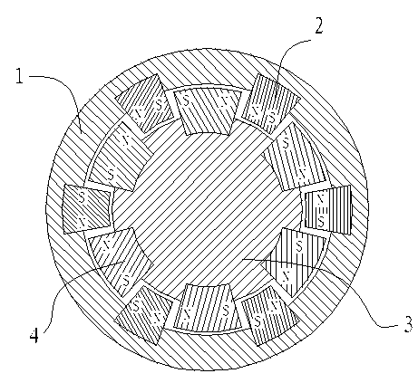
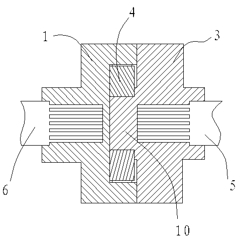
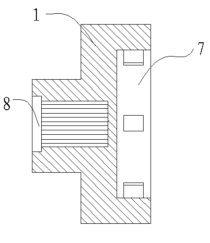
[0018] In the figure, the coupling is composed of a main joint 1 and a slave joint 3, and the end face of the main joint 1 and the slave joint 3 is provided with a circular pit 7, and the axis of the circular pit 7 is in line with the The axis of the main joint 1 is coaxial, and the side walls of the pit 7 are provided with six drive magnets 2, and the drive magnets 2 are evenly distributed along the side walls of the pit 7, and the two adjacent drive magnets 2 There is a gap between them, the matching end surface of the slave joint 3 and the main joint 1 is provided with a pillow block 10, and the side of the pillow block 10 is provided with 6 passive magnetic blocks 4, and the passive magnetic blocks 4 are arranged along the shaft The side walls of the table 10 are evenly distributed, the width of the passive magnetic block 4 is smaller than the ga...


PUM


Abstract

The invention discloses a magnetic resistance coupling, which comprises a master joint and a slave joint which are connected with each other. The end face of the master joint is provided with a round pit; the axis of the round pit is coaxial with that of the master joint; the side wall of the round pit is provided with protruding drive magnetic blocks; the end face of the slave joint is provided with a pillow block; the side face of the pillow block is provided with protruding driven magnetic blocks; the end face of the master joint and the end face of the slave joint are matched; and each driven magnetic block is located in a gap between each two drive magnetic blocks; and the driven magnetic blocks and the fitting surface of the adjacent drive magnetic blocks are same in polarity. The magnetic resistance coupling disclosed by the invention is simple in structure. Compared with a magnetic coupling, the magnetic resistance coupling is higher in transmission torque and cannot be easily damaged.

Description

technical field [0001] The invention relates to a shaft coupling, in particular to a shaft coupling capable of utilizing magnetic field buffering. Background technique [0002] As we all know, a coupling is a mechanical part used to connect two shafts (driving shaft and driven shaft) in different mechanisms so that they rotate together to transmit torque. Couplings are used to transmit torque. In the high-speed and heavy-duty power transmission, some couplings also have the functions of buffering, damping and improving the dynamic performance of the shafting. The coupling consists of two halves, which are respectively connected to the driving shaft and the driven shaft. Most of the general power machines are connected with the working machine by means of couplings, which are the most commonly used connecting parts for shaft transmission of mechanical products. Commonly used couplings include diaphragm couplings, gear couplings, plum blossom couplings, slider couplings, dr...

Claims


Application Information

Patent Timeline
Patent Type & Authority Applications(China)
IPC IPC(8): H02K51/00
Inventor 孟繁茂
Owner SUZHOU CUIZHI NEW TECH DEV
Learn More