Magnetic motor

A magnetic motive and magnetic disk technology, applied in the field of magnetic motive, can solve the problems of not being able to output much power and having no practical value.

Inactive Publication Date: 2013-08-14
王长存
View PDF0 Cites 0 Cited by
  • Summary
  • Abstract
  • Description
  • Claims
  • Application Information

AI Technical Summary

Problems solved by technology

In summary, the above-mentioned power output machines have the above-mentioned deficiencies, which will become more obvious with the depletion of resources and energy in the future, and the continuous deterioration of the environment. Although the current patent office has a large number of magnetic m

Method used


Image

  • Magnetic motor
  • Magnetic motor
  • Magnetic motor

Examples


specific Embodiment

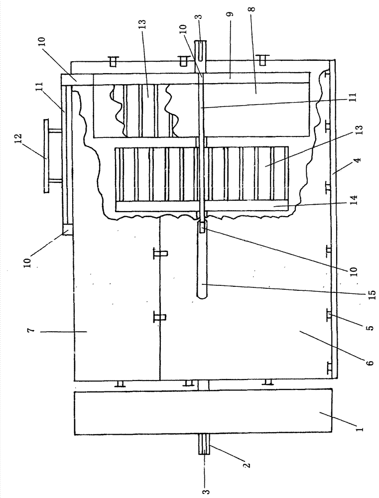
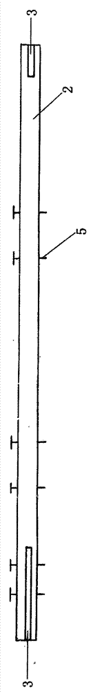
[0007] Specific embodiment: In this embodiment, a dual-disk combination combined with a dual-magnetic coil combination is taken as an example to describe the implementation steps and implementation methods in detail. The first step of parts processing: reference attachment figure 2 Two symmetrical side casing parts 6 are cast out of non-magnetic material. Use a milling machine to mill out two shifting grooves 15 at the position shown in the figure 15, and the left and right positions of the shifting grooves 15 on the other one are opposite. Use a drilling machine to drill four screw holes 16 on the upper butting edge 17, and Drill two screw holes 16 on each of the butt edges 17 at both ends, drill four screw holes 16 on the mounting edge 18, and finally use a tap to tap the threads in all the screw holes 16 to create the side casing part 6 . Reference attachment image 3 Use non-magnetic materials to cast the upper case 7 wool parts. Use a milling machine to mill two shifting...


PUM


Abstract

The invention discloses a magnetic motor which comprises a through shaft penetrating through a casing, as well as a flywheel, wherein at least more than two rotor magnetic discs are arranged on the through shaft; at least more than two stator magnetic discs connected through a disc combining rod are arranged in the casing; at least more than two stator magnetospheres and more than two rotor magnetospheres are arranged on the stator magnetic discs and the rotor magnetic discs respectively; a circle of flat strip-shaped permanent magnets arranged laterally and obliquely are arranged inside each stator magnetosphere and outside each rotor magnetosphere; the same polar planes of all the permanent magnets face outwards; a disc moving groove is formed in the casing, a disc moving handle is further arranged on the disc combining rod; and all parts adopt nonmagnetic materials except the flywheel, the disc combining rod and the disc moving handle. The magnetic motor has the advantages that the characteristic that like permanent magnets repel is used as the power, so that any social resource is not consumed; zero emission and noiselessness are achieved; the environment is not polluted absolutely, and simultaneously, the magnetic motor can output stronger power and has practical application values.

Description

Technical field: [0001] The invention relates to the field of power output machinery, in particular to a permanent magnet that uses the same-sex repulsion characteristics of permanent magnets as power, does not consume any social resources, has zero emission, no noise, and will never pollute the environment, and at the same time, it can output strong power and has practical application value Magnetic motive. Background technique: [0002] The existing power output machinery mainly includes various internal combustion engines and jets that consume fossil fuels, and various electric motors that consume electric power. Various internal combustion engines not only consume a large amount of non-renewable fossil fuels when working, but also emit a large amount of carbon dioxide and other gases into the atmosphere, causing environmental pollution and the greenhouse effect of increasing atmospheric temperature. At the same time, they also emit a large amount of The work is noisy. Altho...

Claims


Application Information

Patent Timeline
IPC IPC(8): H02N11/00
Inventor 王长存
Owner 王长存
Why Eureka
Try Eureka