A low power oscillating circuit
An oscillating circuit and low power consumption technology, which can be applied to the field of power consumption requirements
- Summary
- Abstract
- Description
- Claims
- Application Information
AI Technical Summary
Problems solved by technology
Method used
Image
Examples
no. 1 example
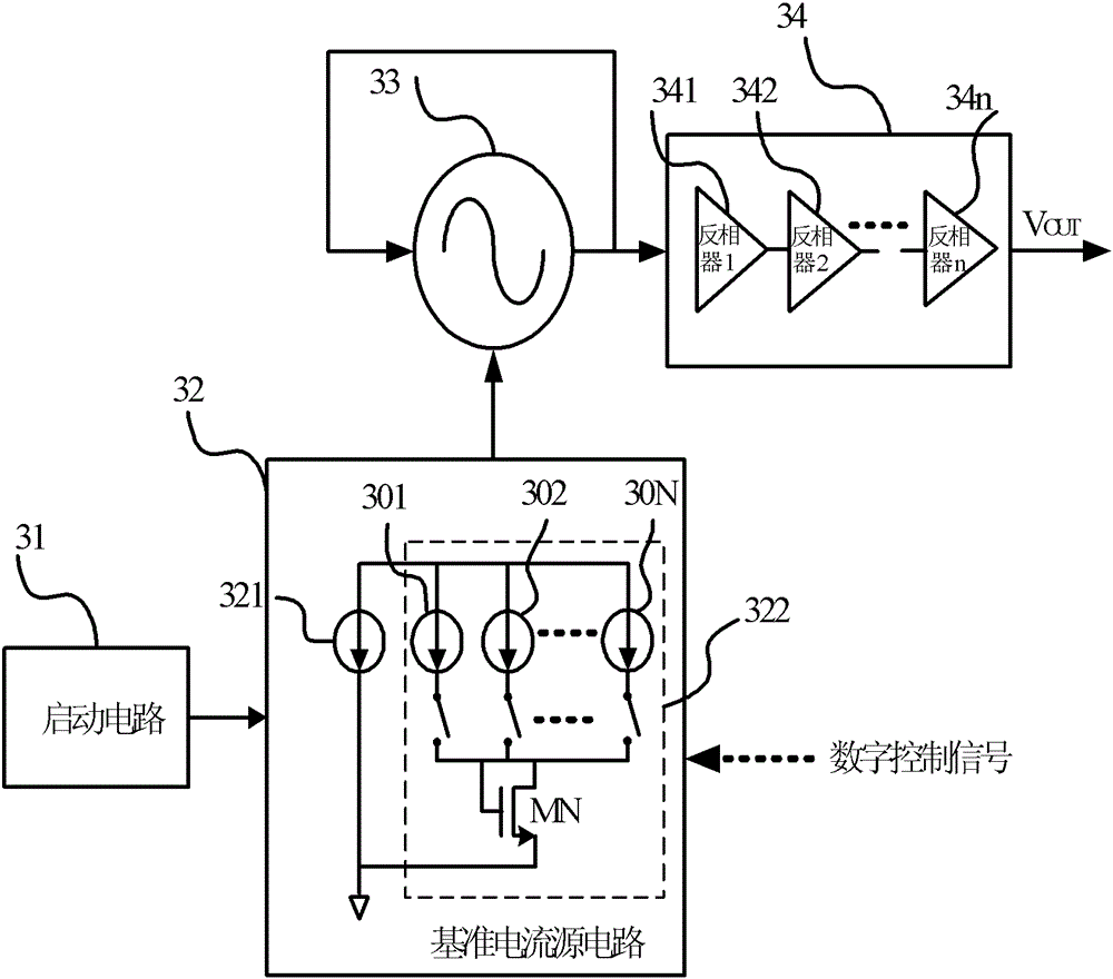
[0074] Figure 3a A block diagram of the low power consumption oscillating circuit of the embodiment of the present invention is given. The low power consumption oscillating circuit is composed of a starting circuit 31 , a reference current source circuit 32 , a controlled oscillating circuit 33 and a driving circuit 34 . The output end of the start-up circuit 31 is connected to the reference current source circuit 32, which is used to change the state of the reference current source circuit 32 from a stable state to a normal working state when powered on. The reference current source circuit 32 includes a constant current source 321 which is a cell reference current source circuit. The reference current source circuit 32 also includes a configurable current source group 322, which includes N mirror current sources 301, 302, ~ 30N, and their currents are all mirrored to the current of the constant current source 321, but the mirror current sources 301, 302, The size of the m...
no. 2 example
[0076] Figure 3bA block diagram of the low power consumption oscillation circuit in which N is 3 according to the embodiment of the present invention is given. The reference current source circuit 32 includes a constant reference current source 321 and a configurable current source 322, the constant tail current source circuit 321 is a reference current source, and the configurable tail current source circuit 322 includes 3 mirror current sources 301 and 302 and 303, they are all mirrored to the mirror current of the constant tail current source 321, but the size of the mirror current is respectively 2, 4, and 6 times of the current of the constant tail current source 321, and also includes the control switch module and the current summary tube MN, the control switch module is controlled by Controlled by an external digital control signal, the current configurable control signal comes from an external digital control signal. The controlled oscillation circuit 33 is supplied ...
no. 3 example
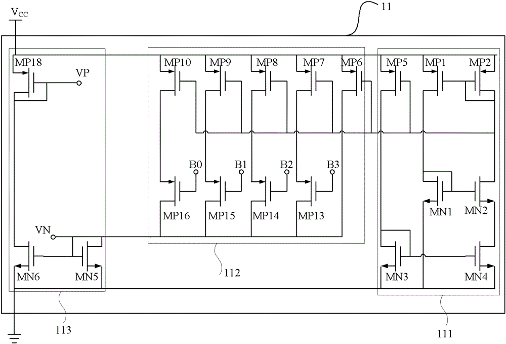
[0078] Figure 4a The schematic diagram of the block diagram of the reference tail current source circuit of the starting circuit and the reference current source circuit of the embodiment of the present invention is given, Figure 4b A schematic diagram of the reference tail current source circuit of the startup circuit and the reference current source circuit of the embodiment of the present invention is given, and the connection relationship between the startup circuit 44 and the reference tail current source circuit is also shown in the figure.
[0079] Such as Figure 4a As shown, the connection relationship between the block diagram of the constant reference current source circuit and the block diagram of the startup circuit and the configurable mirror current source circuit is given. The starting circuit 31 makes the state of the positive current circuit 41 and the negative current circuit 42 of the constant reference current source circuit enter the normal working sta...
PUM
 Abstract
Description
Claims
Application Information
 - R&D
- Intellectual Property
- Life Sciences
- Materials
- Tech Scout
- Unparalleled Data Quality
- Higher Quality Content
- 60% Fewer Hallucinations
Browse by: Latest US Patents, China's latest patents, Technical Efficacy Thesaurus, Application Domain, Technology Topic, Popular Technical Reports.
© 2025 PatSnap. All rights reserved.Legal|Privacy policy|Modern Slavery Act Transparency Statement|Sitemap|About US| Contact US: help@patsnap.com


