Super-power loudspeaker

A super-power, loudspeaker technology, applied in sensors, electrical components, etc., can solve problems such as failure to retrieve, and achieve the effect of good heat dissipation, large bonding surface, and not easy to degumming

Active Publication Date: 2013-08-14
嘉善迪蒙尔电子有限公司
View PDF3 Cites 0 Cited by
  • Summary
  • Abstract
  • Description
  • Claims
  • Application Information

AI Technical Summary

Problems solved by technology

After searching, the new technical solution could not be retrieved

Method used


Image

  • Super-power loudspeaker
  • Super-power loudspeaker

Examples


Embodiment Construction

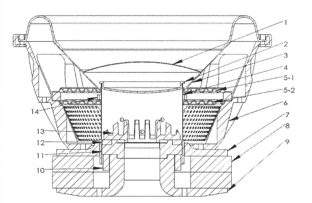
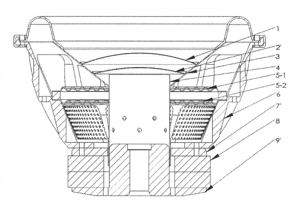
[0015] A super-high-power loudspeaker, comprising at least a pot frame 6, a magnetic steel 8, a T iron 9, a splint 7, a voice coil 4, a paper cone 3, upper and lower dustproof caps 1, 2, and upper and lower spring plates 5-1, 5-2, there is a shaft through hole on the axis of the T iron 9, and there is a group of breathing holes on the voice coil 4, which is characterized in that:

[0016] The lower part of the middle column of the T iron 9 is fitted with a lower short-circuit cooling ring 10, while the upper part of the middle column is fitted with an upper short-circuit cooling ring 12;

[0017] There is an integrated short ring boss on the circumference above the center hole of splint 7;

[0018] The lower dustproof cap 2 has a spherical surface protruding to the inside of the voice coil 4, and its stepped wall matches and is fixed with the inner wall of the upper mouth of the voice coil 4, and the outer edge of the lower dustproof cap 2 is respectively fixed with the upper ...


PUM


Abstract

The invention discloses a super-power loudspeaker. Each T-yoke is formed by tight matching of an upper piece and a lower piece; an upper short-circuit radiating ring and a lower short-circuit radiating ring are matched tightly in each matching position and are placed in a voice coil; a radiator is arranged on each upper piece of each T-yoke; a reinforcing ring is bonded above a position where each lower spring plate is bonded with the voice coil; and a lower dust cap is provided with a spherical surface bulging to the inside of the voice coil, the step wall of the lower dust cap is matched and fixed with the inner wall of the voice coil, and the outer edge is fixed with the upper opening and a paper cone of the voice coil respectively. Experiments prove that a sample of the super-power loudspeaker cannot fail caused by heat radiation and degumming under conditions of extreme power and long-time operation.

Description

technical field [0001] The present invention belongs to the loudspeaker subclass in the International Patent Classification Table, that is, HO4R, and particularly relates to high-power loudspeakers. Background technique [0002] Known public ultra-high-power loudspeaker, at least basin support, magnetic steel, splint, T iron, short-circuit cover, voice coil, paper cone, upper and lower dustproof caps and upper and lower spring plates. Due to the huge working power, there is a lot of accumulated heat. Therefore, under the premise of ensuring the mechanical properties, heat dissipation should be carried out as soon as possible, and material saving should also be considered. For example, two upper and lower dust caps are used, but it will be difficult to apply glue on the lower part, and it is easy to degumming here; another example, the effect of the short-circuit cover is not ideal, and the T-iron will become red when it is operated at extreme power for a long time; Another ...

Claims


Application Information

Patent Timeline
Patent Type & Authority Applications(China)
IPC IPC(8): H04R9/02H04R9/06
Inventor 刘耀华
Owner 嘉善迪蒙尔电子有限公司
Why Eureka
Try Eureka