
A motion distribution mechanism for a horizontal milling and boring machine

A technology of motion distribution and distribution mechanism, which is applied in the direction of driving devices, boring/drilling, metal processing machinery parts, etc., can solve the problems of complex structure, low transmission efficiency, lengthy transmission chain, etc., achieve simple mechanical structure and improve positioning Accuracy, the effect of improving transmission efficiency

Active Publication Date: 2016-08-03
SHENYANG MASCH TOOL CO LTD
View PDF6 Cites 0 Cited by
  • Summary
  • Abstract
  • Description
  • Claims
  • Application Information

AI Technical Summary

Problems solved by technology

[0003] In the original ordinary horizontal milling and boring machine, the main motion is transmitted by the ordinary AC motor to the main shaft through multiple sets of gears on multiple transmission shafts. This structure causes the internal structure of the spindle box to be complicated, the number of gears is large, and the failure rate is high; the usual feed motion in the prior art is driven by an AC motor installed at the right end of the bed, and is transmitted through multiple sets of transmission shafts and forward and reverse mechanisms. The light rod shaft transmits the motion to the lead screw or rack of each moving part through the light rod, so that each feed shaft can obtain 18 kinds of feed; the structure is complicated, the transmission chain is lengthy, the transmission efficiency is low, and the failure rate is high

Method used


Image

  • A motion distribution mechanism for a horizontal milling and boring machine
  • A motion distribution mechanism for a horizontal milling and boring machine
  • A motion distribution mechanism for a horizontal milling and boring machine

Examples


Embodiment 1

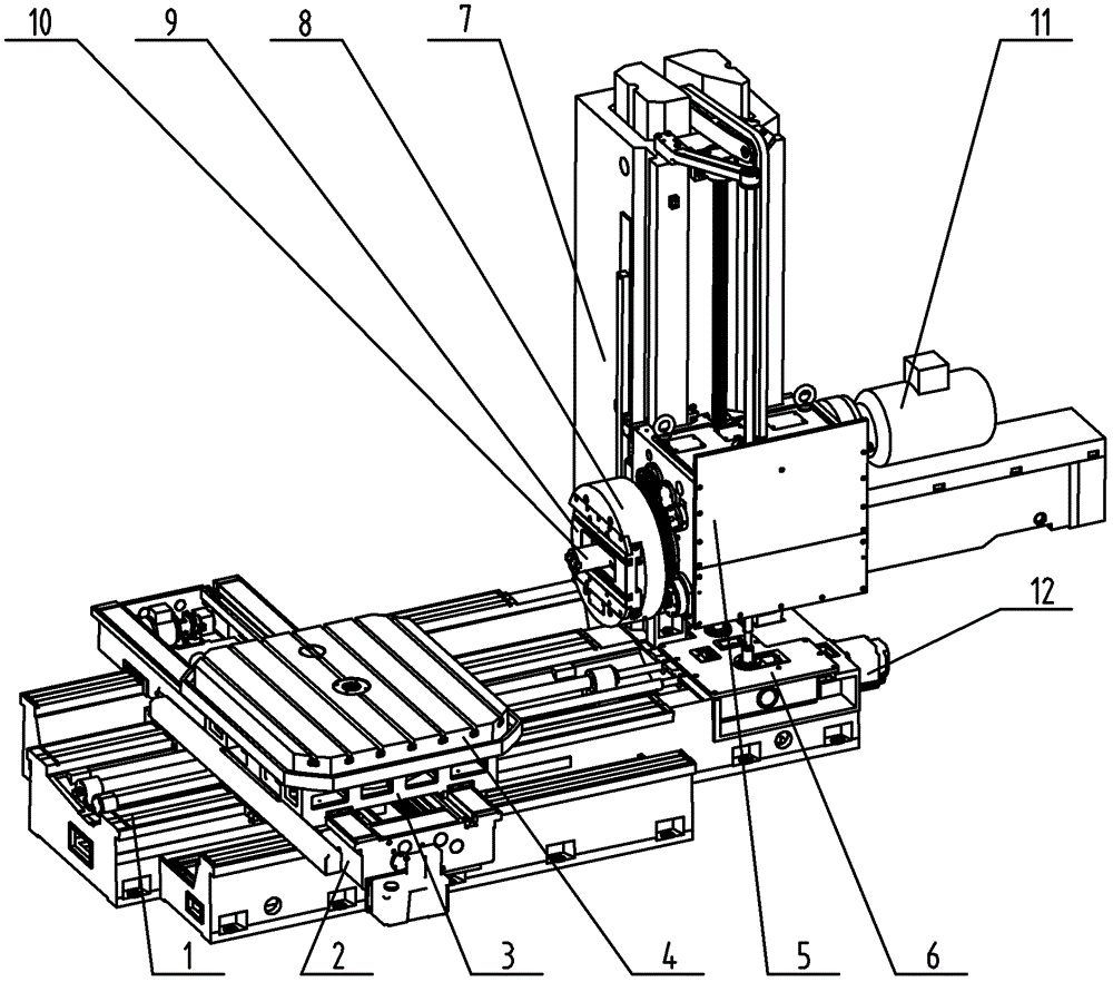
[0025] A motion distribution mechanism for a horizontal milling and boring machine (we call it "horizontal milling and boring machine AH110" or "AH110 automatic milling and boring machine"), which is a part of the horizontal milling and boring machine AH110; The machine consists of the following parts: bed 1, lower slide 2, upper slide 3, worktable 4, spindle box 5, distribution box 6, column 7, boring shaft 10, frequency conversion motor 11, servo motor 12 and electrical system ;

[0026] Among them: the lower seat 2 is arranged on the bed 1, the upper slide 3 is arranged above the lower seat 2 and the two are connected together; between the lower seat 2 and the bed 1 and between the upper slide 3 and the lower seat 2 There are connecting structures such as guide rails; the workbench 4 is arranged on the upper slide 3; the upper part of the horizontally arranged bed 1 near the end is provided with a distribution box 6 and a column 7, and the end of the distribution box 6 away...

Embodiment 2

[0036] A motion distribution mechanism for a horizontal milling and boring machine, which belongs to a part of the horizontal milling and boring machine AH110; Table 4, spindle box 5, distribution box 6, column 7, boring shaft 10, frequency conversion motor 11, servo motor 12 and electrical system;

[0037] Among them: the lower seat 2 is arranged on the bed 1, the upper slide 3 is arranged above the lower seat 2 and the two are connected together; between the lower seat 2 and the bed 1 and between the upper slide 3 and the lower seat 2 There are connecting structures such as guide rails; the workbench 4 is arranged on the upper slide 3; the upper part of the horizontally arranged bed 1 near the end is provided with a distribution box 6 and a column 7, and the end of the distribution box 6 away from the workbench 4 is provided with a Servo motor 12, vertically arranged column 7 is arranged at the near end of that end of lathe bed 1 near distribution box 6; Headstock 5 is arran...

Embodiment 3

[0044] A motion distribution mechanism for a horizontal milling and boring machine, which belongs to a part of the horizontal milling and boring machine AH110; Table 4, spindle box 5, distribution box 6, column 7, boring shaft 10, frequency conversion motor 11, servo motor 12 and electrical system;

[0045] Among them: the lower seat 2 is arranged on the bed 1, the upper slide 3 is arranged above the lower seat 2 and the two are connected together; between the lower seat 2 and the bed 1 and between the upper slide 3 and the lower seat 2 There are connecting structures such as guide rails; the workbench 4 is arranged on the upper slide 3; the upper part of the horizontally arranged bed 1 near the end is provided with a distribution box 6 and a column 7, and the end of the distribution box 6 away from the workbench 4 is provided with a Servo motor 12, vertically arranged column 7 is arranged at the near end of that end of lathe bed 1 near distribution box 6; Headstock 5 is arran...


PUM


Abstract

A movement distribution mechanism for a horizontal milling and boring machine belongs to a part of the complete horizontal milling and boring machine. The complete machine comprises a body (1), a lower sliding seat (2), an upper sliding seat (3), a worktable (4), a spindle box (5), a vertical column (7), a boring shaft (10), a variable frequency motor (11), a servo motor (12) and an electric system. The movement distribution mechanism is characterized in that a main movement distribution mechanism is arranged in the spindle box (5), distribution mechanisms for feed movements in various directions are arranged in a distribution box (6), and a facing head (8) and a facing head slider (9) are arranged in the movement distribution mechanism for the horizontal milling and boring machine. The movement distribution mechanism particularly has the advantages that the movement distribution mechanism is simple in mechanical structure, high in transmission efficiency and low in failure rate, infinitely variable speed can be realized, and a transmission chain is short.

Description

technical field [0001] The invention relates to the technical field of machine tool structure design, especially the technical field of transmission and power system design and application, and particularly provides a motion distribution mechanism for a horizontal milling and boring machine. Background technique [0002] The horizontal milling and boring machine is a universal machine tool, which can perform drilling, boring, reaming, reaming, countersinking, milling, and threading on large parts such as boxes, shells, and machine bases. This type of machine tool is widely used in energy, transportation, heavy-duty, petrochemical machinery and other industries, and is the key equipment for processing box-type parts. [0003] In the original ordinary horizontal milling and boring machine, the main motion is transmitted by the ordinary AC motor to the main shaft through multiple sets of gears on multiple transmission shafts. This structure causes the internal structure of the...

Claims


Application Information

Patent Timeline
Patent Type & Authority Patents(China)
IPC IPC(8): B23B39/02B23Q5/16B23Q5/34
CPCY02P70/10
Inventor 韩涛易刚张文生苗壮王显春邓开楠张宝辉张昊钱颖娟
Owner SHENYANG MASCH TOOL CO LTD
Learn More