Conveying device for yarns

A conveying device and yarn technology, which is applied in the directions of transportation and packaging, conveying filamentous materials, thin material processing, etc., can solve the problems of high cost of production equipment, affecting the working efficiency of textile equipment, and the complexity of textile equipment, etc., to achieve improvement The effect of production efficiency

Active Publication Date: 2013-08-21
江苏舒跑科技有限公司
View PDF6 Cites 2 Cited by
  • Summary
  • Abstract
  • Description
  • Claims
  • Application Information

AI Technical Summary

Problems solved by technology

[0002] As we all know, the yarn delivery device generally provides yarn to the textile equipment under the guidance of multiple roller pairs, and the yarn supply is controlled by the rotation speed of the rollers At the same time, the tension of the yarn is controlled by the rollers. Therefore, each roller pair needs a driving mechanism, which makes the textile equipment more complicated and the cost of the production equipment is higher. At the same time, when the yarn (thread) is supplied, it is inevitable that the yarn will be broken. (thread) phenomenon, but the roller still rotates normally after the yarn is broken, and it is not easy to be discovered by the operator, which directly affects the working efficiency of the textile equipment

Method used


Image

  • Conveying device for yarns
  • Conveying device for yarns

Examples


Embodiment Construction

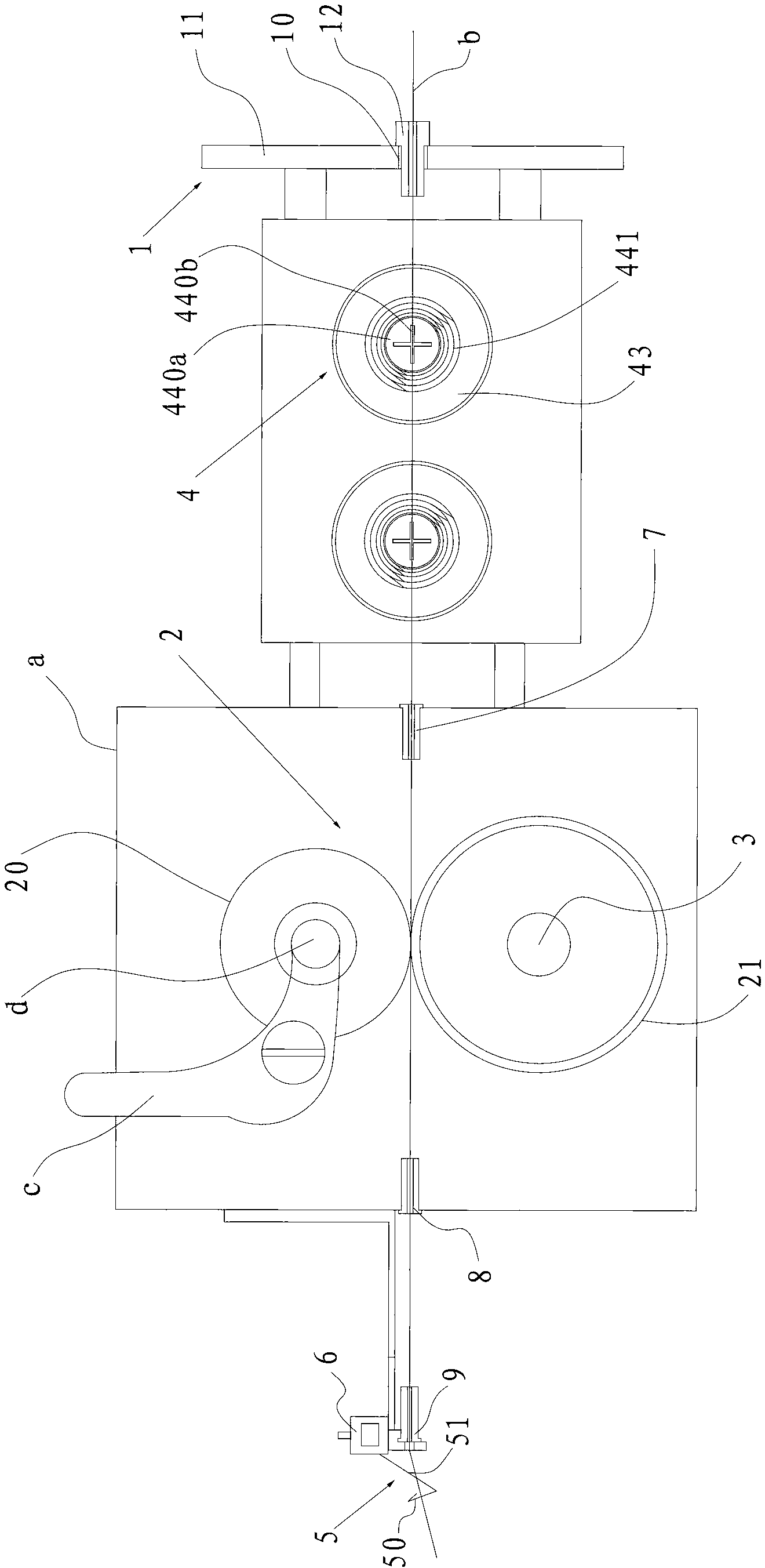
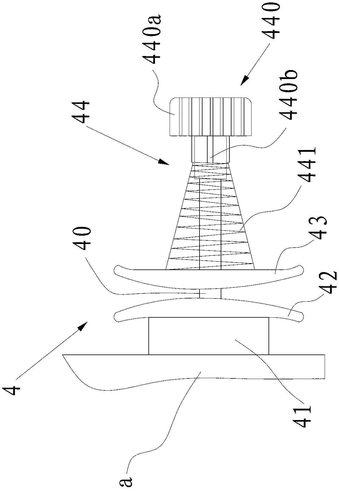
[0018] Such as figure 1 with figure 2 As shown, the yarn delivery device of this embodiment includes a thread passer 1 and a roller pair 2 fixed on the frame a, a driving mechanism for driving the roller pair 2 to rotate relatively, and a roller pair 2 and the thread passer A plurality of tension clamps 4 between 1, a wire hook 5 and a wire breakage sensor 6 arranged at the outlet of the roller pair 2, wherein the roller pair 2 includes an upper roller 20 and a lower roller 21, and the lower roller 21 is fixedly arranged on the drive mechanism On the driving shaft 3, the upper roller 20 can rotate around its own axis, the upper roller 20 is pressed on the lower roller 21, the tension clamp 4 is used to adjust the tightness of the yarn b, the wire hook 5 includes a wire hook 50 and a hook handle 51, One end of the thread breakage sensor 6 is in communication with the driving mechanism, and a contact point is arranged in the other end. When the yarn b passes through the wi...


PUM


Abstract

The invention relates to a conveying device for yarns. The conveying device comprises a yarn winder, a roller pair and a driving mechanism, the roller pair comprises an upper roller and a lower roller, the lower roller is fixedly arranged on a driving shaft of the driving mechanism, the upper roller can rotate around the axis of itself, and the upper roller is arranged on the lower roller in a pressing mode. The conveying device for yarns is characterized in that the conveying device further comprises a plurality of tension clamps arranged between the roller pair and the yarn winder, a yarn guiding hook and a yarn breakage sensor, wherein the yarn guiding hook and the yarn breakage sensor are arranged on a yarn outlet of the roller pair, the tension clamps are used for adjusting tightness degree of the yarns, the yarn guiding hook comprises a yarn hook and a hook handle, one end portion of the yarn breakage sensor is communicated with the driving mechanism, a contact is arranged at the other end portion of the yarn breakage sensor, and when the yarns pass by the yarn hook, a hook handle is not contacted with a contact, and when the yarns do not pass by the yarn hook, the hook handle is contacted with the contact. According to the conveying device for yarns, tightness degree of the yarns is adjusted by the tension clamps, and meanwhile after the yarns are broken, the driving mechanism stops working, an operator easily finds the yarn breakage, so that production efficiency of a textile device is improved.

Description

technical field [0001] The invention relates to a textile machinery equipment, in particular to a yarn conveying device. Background technique [0002] As we all know, the yarn delivery device generally provides yarn to the textile equipment under the guidance of a plurality of roller pairs. Each roller pair requires a driving mechanism, which complicates the textile equipment and increases the cost of the production equipment. At the same time, when the yarn (thread) is supplied, it is inevitable that the yarn (thread) will be broken, but the roller will still rotate normally after the yarn is broken. It is not easy to be found by the operator, which directly affects the working efficiency of the textile equipment. Contents of the invention [0003] The technical problem to be solved by the present invention is to overcome the deficiencies of the prior art and provide an improved yarn delivery device. [0004] In order to solve the above technical problems, the present i...

Claims


Application Information

Patent Timeline
Patent Type & Authority Applications(China)
IPC IPC(8): B65H59/20B65H63/024
Inventor 严惠良严海铭
Owner 江苏舒跑科技有限公司
Why Eureka
Try Eureka