A Phase Synchronization Method of External Input Signal of RF Power Supply

A technology of radio frequency signal and radio frequency power supply, applied in the direction of circuits, discharge tubes, electrical components, etc., can solve problems such as process failure, plasma oscillation, and glow instability, and achieve low cost, eliminate signal phase difference, and improve The effect of process stability

Active Publication Date: 2016-12-21
SOI MICRO CO LTD
View PDF5 Cites 0 Cited by
  • Summary
  • Abstract
  • Description
  • Claims
  • Application Information

AI Technical Summary

Problems solved by technology

Usually, the phase synchronization between two RF power supplies in semiconductor process equipment is to use a coaxial cable to connect the RF signal synchronization output end of one RF power supply with the RF signal synchronization input end of another RF power supply, thereby The two RF power supplies use the same RF signal, and it is expected to eliminate the phase difference and avoid crosstalk; however, even if the two RF power supplies are in the same cabinet (or machine), the length of the coaxial cable connecting the two RF power supplies is also limited. at least tens of centimeters
Since the radio frequency frequency commonly used in semiconductor process equipment is 13.56MHz, that is to say, the wavelength in vacuum is only 22.12 meters, while the wavelength in coaxial cables is shorter, generally only about 16 meters, divided into 360 degrees, that is, 4.4 cm The difference is only 1 degree, so the coaxial cable of tens of centimeters will also cause a large phase difference. In some cases, this phase difference is likely to cause plasma oscillation, the glow is unstable, and the process cannot be carried out normally. eventually lead to processing failure

Method used


Image

  • A Phase Synchronization Method of External Input Signal of RF Power Supply
  • A Phase Synchronization Method of External Input Signal of RF Power Supply

Examples


Embodiment Construction

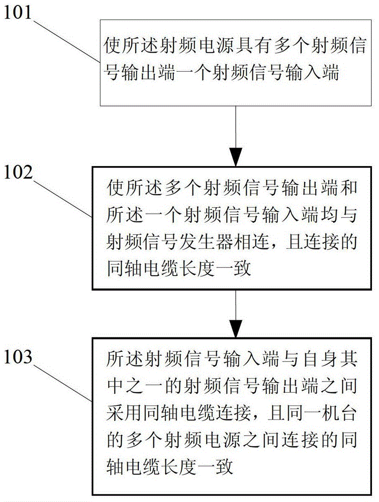
[0020] In order to deeply understand the present invention, the present invention will be described in detail below in conjunction with the accompanying drawings and specific embodiments.

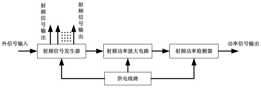
[0021] Such as figure 1 As mentioned above, the embodiment of the present invention discloses a radio frequency power supply, the radio frequency power supply can generally be a tube type radio frequency power supply or a transistor type radio frequency power supply, specifically, the radio frequency power supply includes a radio frequency signal generator, a radio frequency power supply Amplifying circuits, power supply lines and RF power detectors. Wherein, the radio frequency signal generator is respectively connected with the radio frequency power amplifier circuit, the radio frequency power amplifier circuit is connected with the radio frequency power detector, and the power supply line is respectively connected with the radio frequency signal generator, the radio frequency power ampli...


PUM


Abstract

Disclosed is a method for phase synchronization of externally inputted signals of a radiofrequency power supply, comprising: making the radio frequency power supply to be provided with multiple radiofrequency signal output ends and one radiofrequency signal input end; making the multiple radiofrequency signal output ends and the one radiofrequency signal input end to be all connected with a radiofrequency signal generator, where connecting coaxial cables are of a same length; the radiofrequency signal input end connects to one of the radiofrequency signal output ends of self by using a coaxial cable, while connecting coaxial cables between multiple radiofrequency power supplies of a same machine are of a same length. For a path that is passed through by a radiofrequency signal used by the radiofrequency power supplies, the present invention provides the coaxial cables of a same length for transmission of the radiofrequency signal, therefore, signal phase differences between the radiofrequency power supplies of a same machine are eliminated, phase synchronization is maintained, crosstalk is prevented, and process stability is increased. The present invention requires only that the coaxial cables connecting to the external are of a same length and material to implement phase synchronization, thus is not only of reduced costs, but also convenient and expeditious.

Description

technical field [0001] The invention relates to the technical field of radio frequency power supplies, in particular to a method for synchronizing the phase of an external input signal of a radio frequency power supply. Background technique [0002] RF power supply is a device used to generate radio frequency power signals, which is the core component of semiconductor process equipment. All equipment that generates plasma for material processing requires RF power supply to provide energy. Process manufacturing equipment for integrated circuits, solar cells and LEDs (Light Emitting Diodes), such as etching machines, PVD (Physical Vapor Deposition, physical vapor deposition), PECVD (PlasmaEnhanced Chemical Vapor Deposition, plasma enhanced chemical vapor deposition) ), ALD (Atomic Layer Deposition, atomic layer deposition) and other equipment are equipped with RF power supplies of different power specifications. [0003] The RF power supply is generally composed of an RF sign...

Claims


Application Information

Patent Timeline
Patent Type & Authority Patents(China)
IPC IPC(8): H03L7/18H03L7/099
CPCH01J37/32174H01J37/32082
Inventor 李勇滔李英杰夏洋王文东
Owner SOI MICRO CO LTD
Why Eureka
Try Eureka