Radiofrequency power source with adjustable radiofrequency signal phase

A radio frequency signal and radio frequency power supply technology, applied in electrical components, output power conversion devices, plasma and other directions, can solve problems such as large phase difference, processing failure, plasma oscillation, etc., to eliminate signal phase difference and improve process stability , the effect of avoiding crosstalk

Active Publication Date: 2014-06-11
SOI MICRO CO LTD
View PDF8 Cites 2 Cited by
  • Summary
  • Abstract
  • Description
  • Claims
  • Application Information

AI Technical Summary

Problems solved by technology

Usually, the phase synchronization between two RF power supplies in semiconductor process equipment is to use a coaxial cable to connect the RF signal synchronization output end of one RF power supply with the RF signal synchronization input end of another RF power supply, thereby The two RF power supplies use the same RF signal, and it is expected to eliminate the phase difference and avoid crosstalk; however, even if the two RF power supplies are in the same cabinet (or machine), the length of the coaxial cable connecting the two RF power supplies is also limited. at least tens of centimeters
Since the radio frequency frequency commonly used in semiconductor process equipment is 13.56MHz, that is to say, the wavelength in vacuum is only 22.12 meters, while the wavelength in coaxial cables is shorter, generally only about 16 meters, divided into 360 degrees, that is, 4.4 cm The difference is only 1 degree, so the coaxial cable of tens of centimeters will also cause a large phase difference. In some cases, this phase difference is likely to cause plasma oscillation, the glow is unstable, and the process cannot be carried out normally. eventually lead to processing failure

Method used


Image

  • Radiofrequency power source with adjustable radiofrequency signal phase
  • Radiofrequency power source with adjustable radiofrequency signal phase
  • Radiofrequency power source with adjustable radiofrequency signal phase

Examples


Embodiment 1

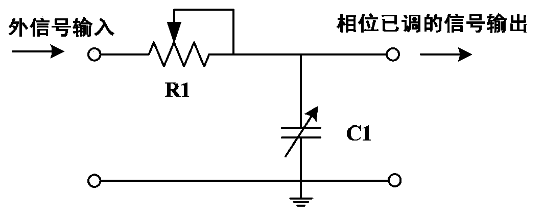
[0031]Such as image 3 As shown, Embodiment 1 discloses a schematic circuit diagram of the phase adjustment circuit in the embodiment of the present invention. The phase adjustment circuit includes two basic components, a potentiometer (or variable resistor) R1 and a variable capacitor C1. One end of the potentiometer R1 is connected to an external input signal, and the other end is connected to one end of the variable capacitor C1. Connected, the other end of the variable capacitor C1 is grounded, and the terminal of the potentiometer R1 and the variable capacitor C1 outputs a phase-adjusted signal. The value range of potentiometer R1 and variable capacitor C1 can be set according to the operating frequency of the RF power supply, for example, the operating frequency of the RF power supply is 13.56MHz, the maximum resistance value of the potentiometer R1 can be 1KΩ, and the maximum capacitance of the variable capacitor C1 is 100pF. Optionally, the maximum resistance range o...

Embodiment 2

[0034] Such as Figure 4 As shown, Embodiment 2 discloses another schematic circuit diagram of the phase adjustment circuit in the embodiment of the present invention. as image 3 A transformation of the way shown, the phase adjustment circuit in this embodiment adds an LC network on the basis of the original circuit, wherein one end of the inductance L1 is connected to the previous stage, and the other end is connected to the variable capacitor C2, the variable capacitor C2 The other end is grounded, and the connected end of the inductor L1 and the variable capacitor C2 outputs a phase-adjusted signal. Generally, adjustable inductors and capacitors can be used, but since the adjustable inductor is expensive and bulky, a fixed inductor is used in this embodiment, and a variable capacitor C2 is used for the capacitor. In this way, the value of the inductor L1 is 1μH to 10μH, the maximum resistance range of the potentiometer R1 can be 100Ω~100KΩ, the maximum capacitance range ...

Embodiment 3

[0037] Such as Figure 5 As shown, Embodiment 3 discloses another schematic circuit diagram of the phase adjustment circuit in the embodiment of the present invention. and Figure 4 Similarly, in this embodiment, the fixed capacitor C3 is used in the phase adjustment circuit to replace the variable capacitor C1 in Embodiment 2. On the one hand, the adjustment can be reduced, and on the other hand, the cost can also be saved. The value range of these devices, the value of inductor L1 is 1μH ~ 10μH, the maximum resistance range of potentiometer R1 can be 100Ω ~ 100KΩ, the capacitance value range of fixed capacitor C1 can be 10pF ~ 1000pF, the maximum capacitance of variable capacitor C2 The value range can be from 10pF to 1000pF.

[0038] In the embodiment of the present invention, potentiometers and variable capacitors use devices with high positioning accuracy, and fixed capacitors and inductors use devices with high Q value.


PUM


Abstract

The invention discloses a radiofrequency power source with an adjustable radiofrequency signal phase. The radiofrequency power source comprises a radiofrequency signal generator, a radiofrequency power amplification circuit, a power supply line and a radiofrequency power detector. The radiofrequency signal generator comprises a phase adjustment circuit. The phase adjustment circuit is used for adjusting the phase of an external input radiofrequency signal. Since the phase adjustment circuit is embedded into the radiofrequency signal generator, the phase of a synchronously accessed radiofrequency signal can be adjusted, the signal phase difference between the radiofrequency power source and a radiofrequency power source which provides the radiofrequency signal can be eliminated, crosstalk is avoided, and the process stability is improved.

Description

technical field [0001] The invention relates to a radio frequency power supply, in particular to a radio frequency power supply with adjustable radio frequency signal phase. Background technique [0002] RF power supply is a device used to generate radio frequency power signals, which is the core component of semiconductor process equipment. All equipment that generates plasma for material processing requires RF power supply to provide energy. Process manufacturing equipment for integrated circuits, solar cells and LEDs (Light Emitting Diodes), such as etching machines, PVD (Physical Vapor Deposition, physical vapor deposition), PECVD (PlasmaEnhanced Chemical Vapor Deposition, plasma enhanced chemical vapor deposition) ), ALD (Atomic Layer Deposition, atomic layer deposition) and other equipment are equipped with RF power supplies of different power specifications. [0003] The RF power supply is generally composed of an RF signal generator, an RF power amplifier circuit, a...

Claims


Application Information

Patent Timeline
Patent Type & Authority Applications(China)
IPC IPC(8): H02M1/00H05H1/46
CPCH03H7/18H05H1/46H05H2242/24
Inventor 李勇滔李英杰夏洋王文东
Owner SOI MICRO CO LTD
Why Eureka
Try Eureka