
Framework swinging alternating type paper pulp molding machine

A pulp molding and forming machine technology, used in textiles and papermaking, can solve the problems of low degree of automation, long processing cycle, large investment, etc., and achieve the effect of high degree of automation, high production efficiency, and simplified production line

Active Publication Date: 2013-08-21
QIQIHAR UNIVERSITY
View PDF7 Cites 1 Cited by
  • Summary
  • Abstract
  • Description
  • Claims
  • Application Information

AI Technical Summary

Problems solved by technology

[0004] The purpose of the present invention is to solve the problems that traditional pulp molding machines have upper and lower molds, which require high precision molds, long processing cycle, large investment and low automation, and provide a frame swing alternate pulp molding machine

Method used


Image

  • Framework swinging alternating type paper pulp molding machine
  • Framework swinging alternating type paper pulp molding machine
  • Framework swinging alternating type paper pulp molding machine

Examples


specific Embodiment approach 1

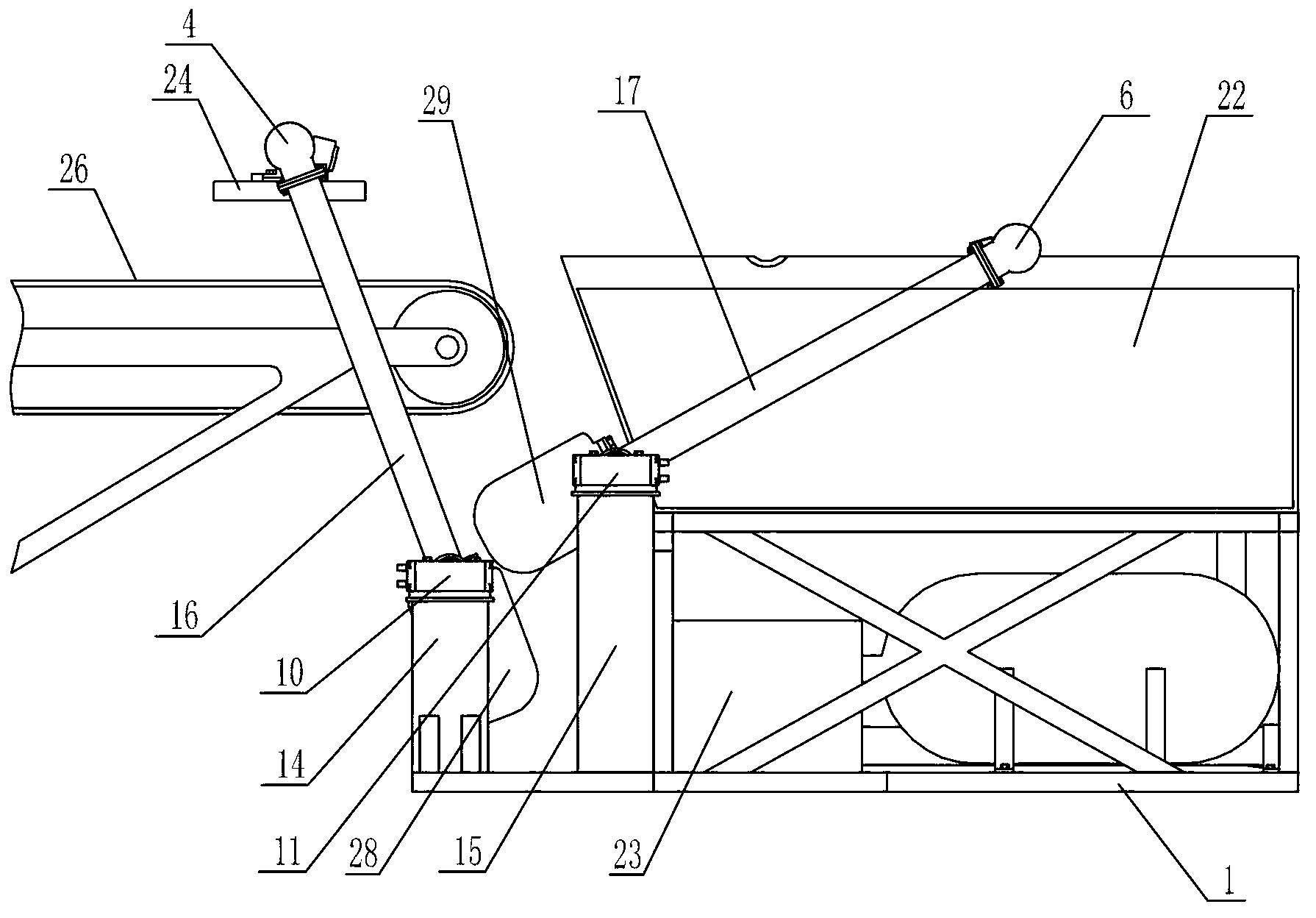
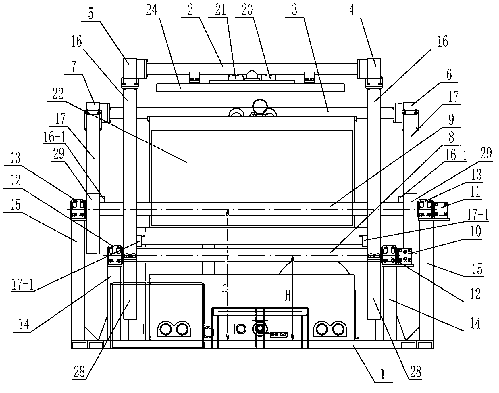
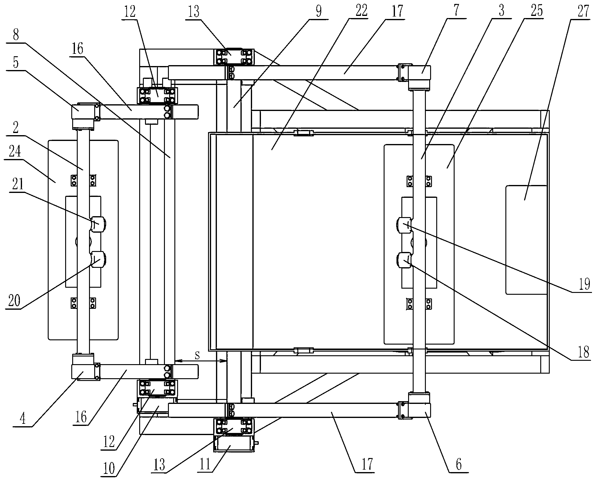
[0013] Specific implementation mode one: combine Figure 1 ~ Figure 3 Describe this embodiment, this embodiment includes a frame 1, a front pipeline 2, a rear pipeline 3, a front vacuum head 4, a front compressed air head 5, a rear vacuum head 6, a rear compressed air head 7, a front spindle 8, Rear main shaft 9, front driving device 10, rear driving device 11, two front bearing blocks 12, two rear bearing blocks 13, two first fixed supports 14, two second fixed supports 15, two front swings Arm 16, two rear swing arms 17, rear pipeline vacuum control valve 18, rear pipeline compressed air control valve 19, front pipeline vacuum control valve 20, front pipeline compressed air control valve 21, pulp tank 22, automatic control box 23, front The mold box 24 and the rear mold box 25, the front pipeline 2 and the rear pipeline 3 are arranged in parallel, the front vacuum head 4 and the front compressed air head 5 are respectively installed at both ends of the front pipeline 2, the ...

specific Embodiment approach 2

[0015] Specific implementation mode two: combination Figure 1 ~ Figure 3To describe this embodiment, the front swing arm 16 and the rear swing arm 17 of this embodiment are both provided with hollow cavities. Allows for easy airflow. Other components and connections are the same as those in the first embodiment.

specific Embodiment approach 3

[0016] Specific implementation mode three: combination figure 2 Describe this embodiment, the height h of the front spindle between the front spindle 8 and the bottom surface of the frame 1 of this embodiment is smaller than the rear spindle height H between the rear spindle 9 and the bottom surface of the frame 1, and the horizontal distance between the front spindle 8 and the rear spindle 9 is S, the length of the front swing arm 16 is equal to the length of the rear swing arm 17. Among them, h, H, and S are obtained by calculation, so that the front mold box 24 and the rear mold box 25 reach the same position above the conveyor belt 26 to ensure uniform feeding. The front mold box 24 and the rear mold box 25 are designed to have a height difference, so that the front mold box 24 and the rear mold box 25 do not interfere with each other. Other components and connections are the same as those in the second embodiment.


PUM


Abstract

The invention relates to a paper pulp molding machine, in particular to a framework swinging alternating type paper pulp molding machine which solves the problems that a traditional paper pulp molding machine is provided with an upper mould and a lower mould, the moulds are poor in precision, processing cycle is long and investment is big. A front pipeline and a rear pipeline are arranged in parallel. A front vacuum air head and a front compressed air head are respectively arranged at two ends of the front pipeline. A rear vacuum air head and a rear compressed air head are respectively arranged at two ends of the rear pipeline. The lower end of the front vacuum air head and the lower end of the front compressed air head are respectively connected with a front swing arm. The lower end of each front swing arm is fixed on a front main shaft. The lower end of the rear vacuum air head and the lower end of the rear compressed air head are respectively connected a rear swing arm. The lower end of each rear swing arm is fixed on a rear main shaft. An input end of the front main shaft is connected with a front driving device, and an input end of the rear main shaft is connected with a rear driving device. A front mould box is arranged below the front pipeline, and a rear mould box is arranged below the rear pipeline. A paper pulp groove is arranged at the back of the rear main shaft. The framework swinging alternating type paper pulp molding machine is applied to production of paper pulp molding products.

Description

technical field [0001] The invention relates to a pulp molding machine, in particular to a frame swing alternate type pulp molding machine. Background technique [0002] The production process of pulp molded products using a pulp molding machine is as follows: a mold with a specific shape and covered with a metal mesh is submerged in the slurry surface, and the mold sucks the slurry through a vacuum pipeline; when the slurry gathers on the surface of the mold to a certain After the thickness is reached, the mold rises until the mold lifts out of the pulp surface, and continues vacuum dehydration to make the product a wet billet; then turn off the vacuum, and then use a compressed air pipe to feed compressed air into the mold to separate the wet billet from the mesh surface. Vacuum suction forming method is the most popular method for paper and plastic products. According to its structure, there are three ways: drum type, flip type and reciprocating lifting type. (1) Drum t...

Claims


Application Information

Patent Timeline
Patent Type & Authority Applications(China)
IPC IPC(8): D21J5/00
Inventor 赵红毛洪厚王志森
Owner QIQIHAR UNIVERSITY
Learn More