Eureka AIR delivers breakthrough ideas for toughest innovation challenges, trusted by R&D personnel around the world.

Cementing buffer

A buffer and cementing technology, applied in wellbore/well components, earthwork drilling, sealing/isolation, etc., can solve the problems of casing retaining cement plugs, inability to effectively reduce the falling speed of cement slurry, and return of cement slurry, etc. problem, to achieve the effect of improving reliability

Active Publication Date: 2016-04-06
CHINA PETROLEUM & CHEM CORP +1
View PDF5 Cites 0 Cited by
  • Summary
  • Abstract
  • Description
  • Claims
  • Application Information

AI Technical Summary

Problems solved by technology

There is a risk that the cover that relies on spring opening and closing cannot be closed. If the lower part of the cement restrictor does not use tools such as floating hoops and floating shoes, it will cause dangers such as backflow of cement slurry and cement plugs in the casing.
The cement restrictor cannot effectively reduce the falling speed of cement slurry

Method used


Image

  • Cementing buffer

Examples


Embodiment Construction

[0026] The present invention will be further described below in conjunction with accompanying drawing.

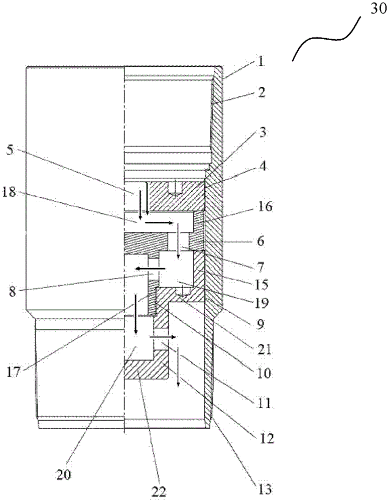
[0027] figure 1 A cementing buffer 30 according to the invention is schematically shown. Such as figure 1 As shown, the cementing buffer 30 includes a casing 1 . Threads are provided at both ends of the housing 1 so as to be connected with adjacent pipe strings (not shown). exist figure 1 In the illustrated embodiment, an internal thread 2 is provided on the inside of the first end of the housing 1 and an external thread 13 is provided on the outside of the second end of the housing 1 .

[0028] A first buffer component is arranged inside the housing 1, such as figure 1 The baffle shown in 3. A first flow hole 5 is arranged on the baffle plate 3 to receive the fluid entering the well. In a preferred embodiment, the first flow hole 5 is arranged at the center of the baffle 3 . The baffle 3 is fixedly connected with the housing 1 . In one embodiment, threads are prov...


PUM


Abstract

The invention relates to a well cementation buffer and belongs to the field of petroleum machinery. The well cementation buffer comprises a casing communicated with a pipe string and a first buffer component arranged in the casing and provided with a first overflowing hole. At least one additional buffer component is arranged on the downstream of a baffle along the fluid flowing direction, an additional overflowing hole is arranged on the additional buffer component, and a curve fluid flowing channel is formed in the buffer. By means of the well cementation buffer, flowing speed of cement slurry can be reduced remarkably, protection of a well cementation tool on the lower portion of the buffer is achieved, and annulus blocking probability can be reduced remarkably.

Description

technical field [0001] The invention relates to a well cementing device, in particular to a dry cementing buffer. Background technique [0002] Gas drilling technology has obvious effects in improving drilling speed, preventing leakage and plugging, discovering and protecting oil and gas layers, etc. However, after gas drilling is completed, in order to perform surface casing or technical casing cementing, water-based drilling fluid needs to be replaced before conventional cementing operations. This process will cause wellbore hydration instability and lost circulation. Because it takes a lot of time and drilling materials to deal with downhole complex situations such as wellbore instability and lost circulation, and it is necessary to gas lift out the drilling fluid after cementing, and continue air drilling after drying the wellbore, so the operation period is long and cannot Access to gas drilling has vested economics. After gas drilling is completed, dry cementing can ...

Claims


Application Information

Patent Timeline
Patent Type & Authority Patents(China)
IPC IPC(8): E21B33/13
Inventor 张明昌周福新刘阳吴姬昊
Owner CHINA PETROLEUM & CHEM CORP
Why Eureka
Eureka Blog
Learn More