Replacing device and method for disc cutters of tool head

A tool replacement and tool head technology, which is applied in earth-moving drilling, mining equipment, tunnels, etc., can solve the problems of long time, longer replacement operation time, and higher cost.

Inactive Publication Date: 2013-08-21
MITSUBISHI HEAVY IND MACHINERY SYST LTD
View PDF4 Cites 19 Cited by
  • Summary
  • Abstract
  • Description
  • Claims
  • Application Information

AI Technical Summary

Problems solved by technology

[0006] However, according to this method, there is such a problem that the cost becomes high because the disk cutter is replaced after the ground improvement is carried out, and in addition, since

Method used


Image

  • Replacing device and method for disc cutters of tool head
  • Replacing device and method for disc cutters of tool head
  • Replacing device and method for disc cutters of tool head

Examples


Embodiment 1

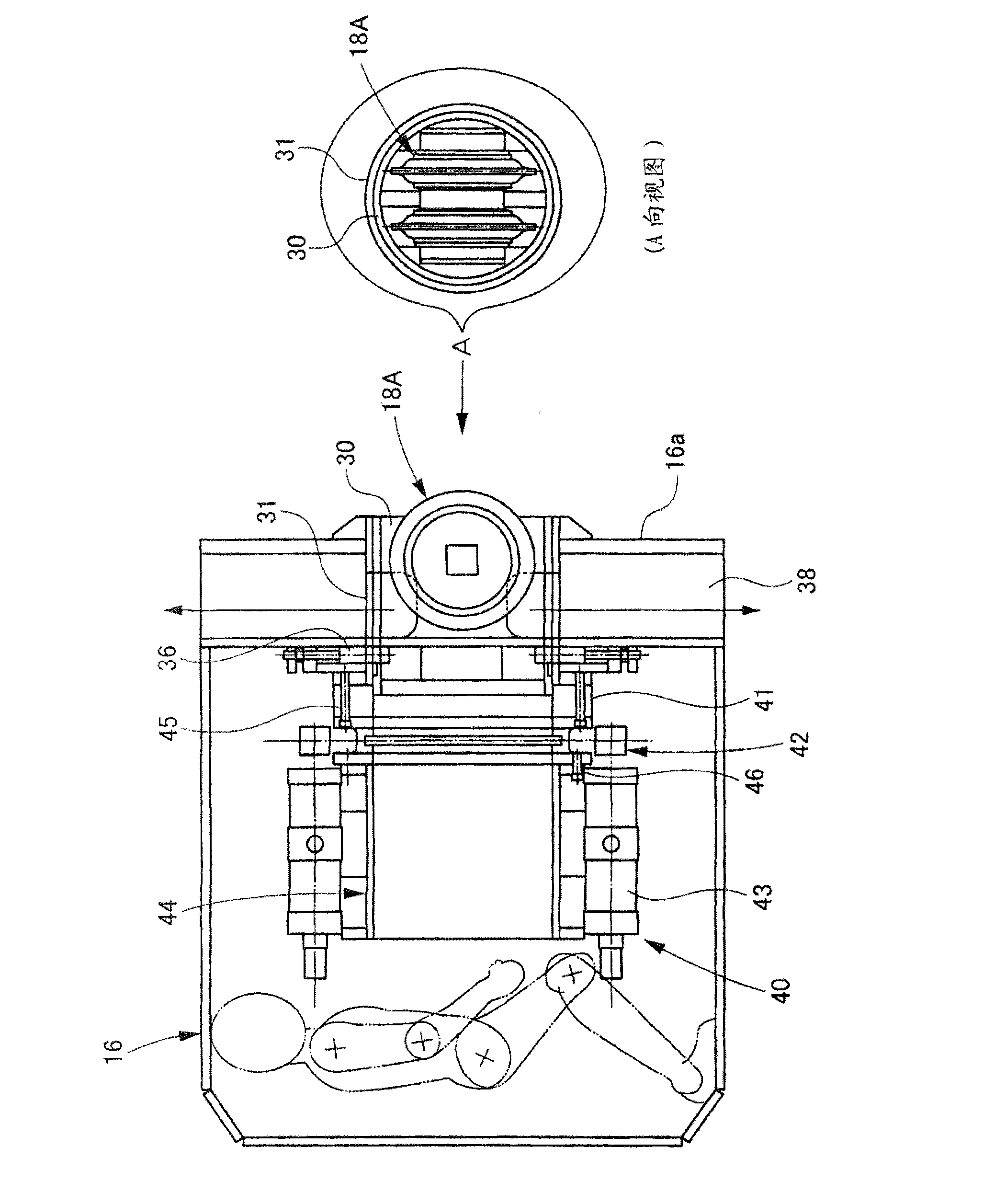
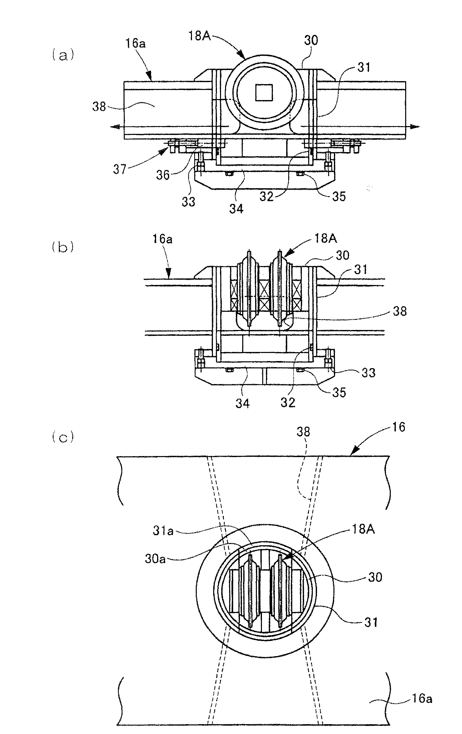
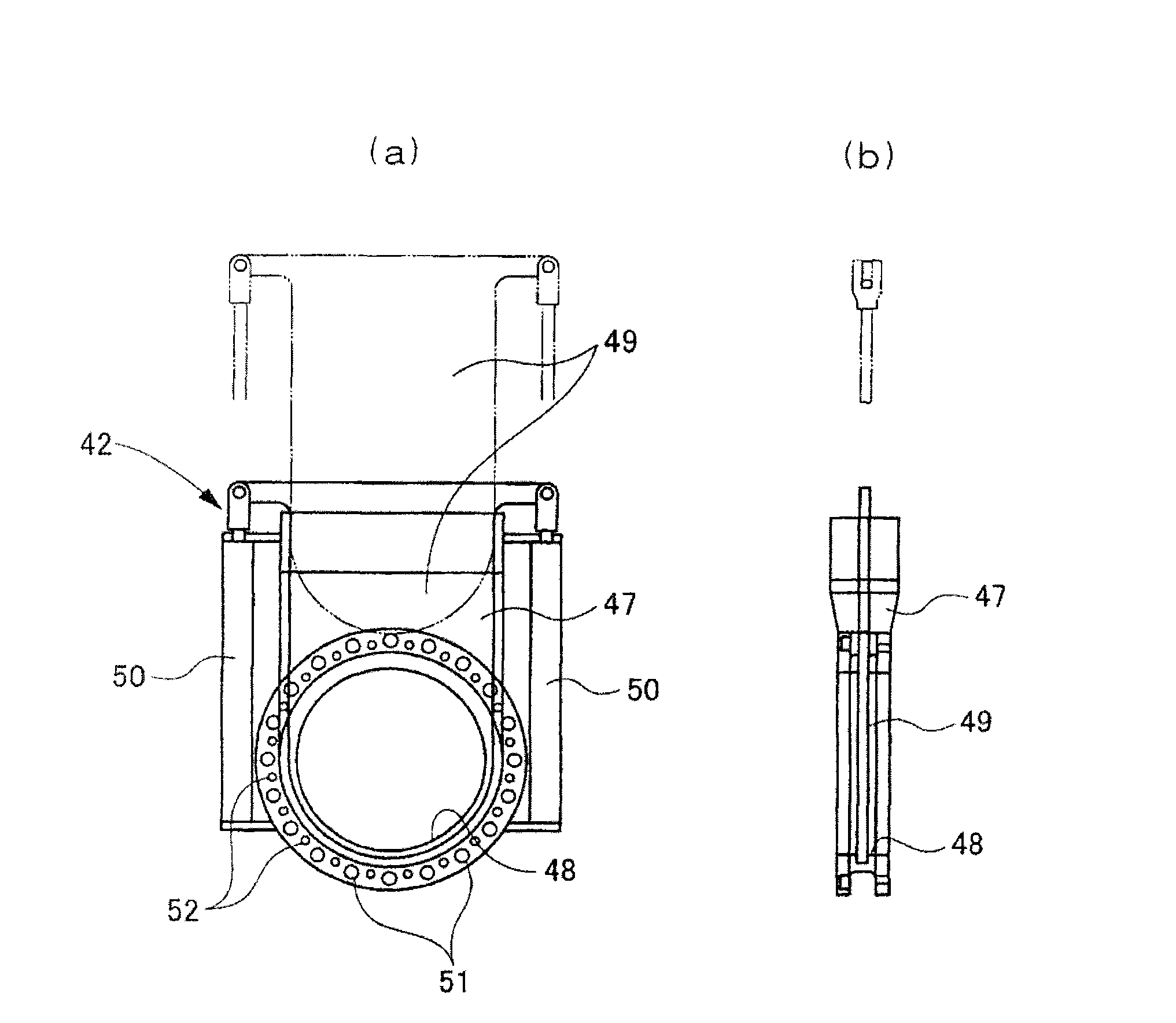
[0098] figure 1 is an overall side view showing the disc cutter changing device of Embodiment 1 of the present invention; figure 2 It is a diagram of the installation state when the disc-shaped cutter is excavated, wherein, figure (a) is a main view, figure (b) is a side view, and figure (c) is a top view; image 3 It is a structural explanatory diagram of a knife gate valve, wherein, figure (a) is a back view, and figure (b) is a side view; Figure 4 is a sectional view of the main parts of the earth pressure shield excavator; Figure 5 It is the front view of the earth pressure shield excavator (cutter head); Image 6 is an explanatory diagram of the replacement steps of the disc cutter; Figure 7 is an explanatory diagram of the replacement steps of the disc cutter; Figure 8 is an explanatory diagram of the replacement steps of the disc cutter; Figure 9 is an explanatory diagram of the replacement steps of the disc cutter; Figure 10 It is an explanatory diagram of...

Embodiment 2

[0141] Figure 12 It is a cross-sectional view showing the spokes of the cutterhead according to Embodiment 2 of the present invention, wherein, figure (a) is an installation state diagram when the disk cutter is excavated, and figure (b) is an installation state diagram when the disk cutter is replaced .

[0142] This is an example in which this disk cutter changing device is applied to a so-called front-loading double disk cutter 18A in which disk cutters are mounted from the front side of the cutter head, instead of the rear-loading double disk cutter 18A of the first embodiment.

[0143] For example, as shown, a dimple 16b is formed extending longitudinally on the front wall portion 16a of the cutter head spoke 16, within which a replaceable dual disc cutter 18A is located and mounted via a sand guide 61.

[0144] Specifically, the short cylindrical mount 30 with the top of the double disk cutter 18A is inserted into the cylindrical mounting table 31 fixedly arranged on t...


PUM


Abstract

The invention provides a replacing device and method for disc cutters of a tool head, which allow operators to replace the disc cutters safely and to arrange the disc cutters at required intervals, with low cost. The replacing device (40) is arranged in the tool head (12) formed by installing a seat frame (30) supporting the replaceable double disc cutter (18A) in a freely rotatable manner through a fixing plate (34) to an installing bed (31). The replacing device can replace the double disc cutter for each seat frame in a cutter disc spoke (16) under atmospheric pressure behind the tool head. The replacing device comprises a sluice valve (42) which can be connected with a rear-end opening of the installing bed in a freely detachable manner and thus takes the place of the fixing plate, a replacing guide member (44) which can be connected with the rear portion of the sluice valve and thus guides the seat frame to move back and forth relative to the installing bed, and a loading and unloading jack (43) which is installed on the replacing guide member for enabling the seat frame to move back and forth.

Description

technical field [0001] The invention relates to a device and a method for changing disc cutters of cutter heads in tunnel excavating machines. Background technique [0002] As is well known, in general, earth pressure shield excavators and the like use disk cutters (also called roller cone bits) in order to prevent chipping or peeling of the blades of the cutter head against the gravel layer. That is, the disc cutter is fixedly attached to the front surface portion of the cutter head with bolts, wedges or the like. [0003] And, when digging into the bedrock layer, boulder layer and digging into a long distance, the disc cutter will be worn and worn out, and the disc cutter needs to be replaced. Conventionally, in such a case, the operator enters into the chamber divided by the partition wall between the cutter head and the excavator body, removes fixing parts such as bolts and wedges, and replaces the disc cutter. [0004] Therefore, there is such a problem that under the...

Claims


Application Information

Patent Timeline
IPC IPC(8): E21D9/08
Inventor 熊尾义光村上贤上村城司田中茂
Owner MITSUBISHI HEAVY IND MACHINERY SYST LTD
Why Eureka
Try Eureka