Gear pumps and construction machinery

A gear pump and pump body technology, which is applied in the direction of mechanical equipment, pumps, pump components, etc., can solve the problems of gear pump bearings and seals, entering the engine or gearbox, affecting service life, etc.

Active Publication Date: 2016-04-20
ZOOMLION HEAVY IND CO LTD
View PDF8 Cites 0 Cited by
  • Summary
  • Abstract
  • Description
  • Claims
  • Application Information

AI Technical Summary

Problems solved by technology

The defect of the above-mentioned first installation method is: due to reasons such as production, installation, and transmission shaft strength, it is impossible to achieve absolute coaxiality between the output shaft of the engine or gearbox, the transmission shaft, and the input shaft of the gear pump. There will always be jumping or stringing between them. In this way, when the transmission shaft is in the process of rapid rotation, due to the existence of jumping, it is bound to have an impact on the bearings and seals of the gear pump, engine or gearbox. After a long time of operation, it must be Affect its service life; the defect of the above-mentioned second installation method is: because the gear pump is directly installed on the engine or gearbox, when the gear pump shaft seal is aging, damaged and oil leaks, the hydraulic oil will enter the engine or transmission In the box, affecting its lubrication system or causing it to burn out

Method used


Image

  • Gear pumps and construction machinery
  • Gear pumps and construction machinery

Examples


Embodiment Construction

[0030] Specific embodiments of the present invention will be described in detail below in conjunction with the accompanying drawings. It should be understood that the specific embodiments described here are only used to illustrate and explain the present invention, and are not intended to limit the present invention.

[0031] In the present invention, in the case of no contrary description, the used orientation words such as "up, down, left and right" usually refer to the up, down, left and right shown in the accompanying drawings; "inside and outside" Refers to the inside and outside of the outline of each part itself.

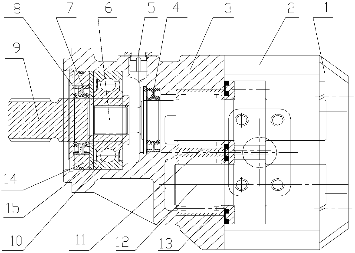
[0032] According to one aspect of the present invention, as figure 1 As shown, a gear pump is provided, which includes a front end cover 1, a rear end cover 3 and a pump body 2 connected between the front end cover 1 and the rear end cover 3, and the pump body 2 has a protruding rear end cover 3 Transmission input shaft 6, wherein the gear pump also include...


PUM


Abstract

The invention discloses a gear pump comprising a front end cover (1), a rear end cover (3) and a pump body (2) connected between the front end cover (1) and the rear end cover (3), wherein the pump body (2) is provided with a transmission output shaft (6) stretching out of the rear end cover; the gear pump further comprises a connection module; the connection module comprises an end cover (8) and a module shaft (9); the end cover (8) and the rear end cover (3) are fixedly connected; one end of the module shaft (9) is connected with the transmission output shaft (6); and the other end of the module shaft (9) stretches out of the module end cover (8). Furthermore, the invention further discloses an engineering machine comprising the gear pump. The connection module not only guarantees the coaxality between an output shaft of an engine or a speed changing box and the gear pump, but also prevents hydraulic oil from leaking into the engine or the speed changing box.

Description

technical field [0001] The invention relates to a hydraulic transmission system of an engineering machine, in particular to a gear pump and an engineering machine including the gear pump. Background technique [0002] At present, in the field of hydraulic transmission, gear pumps have been widely used as power sources because of their low cost and simple system design. In terms of gear pump installation, there are usually two installation methods in the prior art. The first is to connect the gear pump to the engine or gearbox through a transmission shaft, etc.; the second is to directly install the gear pump on the engine or transmission. on the box. The defect of the above-mentioned first installation method is that due to reasons such as production, installation, and transmission shaft strength, it is impossible to achieve absolute coaxiality between the output shaft of the engine or the gearbox, the transmission shaft, and the input shaft of the gear pump. There will al...

Claims


Application Information

Patent Timeline
Patent Type & Authority Patents(China)
IPC IPC(8): F04C15/00F04C11/00
Inventor 蒯胜龙冶国胡廷江
Owner ZOOMLION HEAVY IND CO LTD
Why Eureka
Try Eureka