
Impeller and centrifugal compressor including the impeller

An impeller and blade technology, applied in the field of centrifugal compressors, can solve problems such as impeller efficiency cannot be further improved, separation loss, etc., and achieve the effects of widening the scope of high-efficiency area, reducing surge flow, and improving impeller efficiency

Active Publication Date: 2015-08-26
GREE ELECTRIC APPLIANCES INC
View PDF5 Cites 0 Cited by
  • Summary
  • Abstract
  • Description
  • Claims
  • Application Information

AI Technical Summary

Problems solved by technology

[0008] The present invention aims to provide an impeller and a centrifugal compressor including the impeller, so as to solve the technical problem in the prior art that there is flow separation at the blade inlet and other positions of the impeller, resulting in separation loss, so that the efficiency of the impeller cannot be further improved

Method used


Image

  • Impeller and centrifugal compressor including the impeller
  • Impeller and centrifugal compressor including the impeller
  • Impeller and centrifugal compressor including the impeller

Examples


Embodiment Construction

[0028] It should be noted that, in the case of no conflict, the embodiments in the present application and the features in the embodiments can be combined with each other. The present invention will be described in detail below with reference to the accompanying drawings and examples.

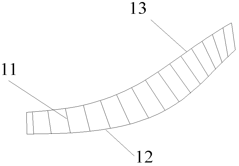
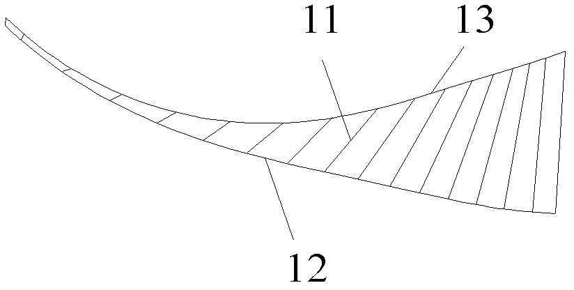
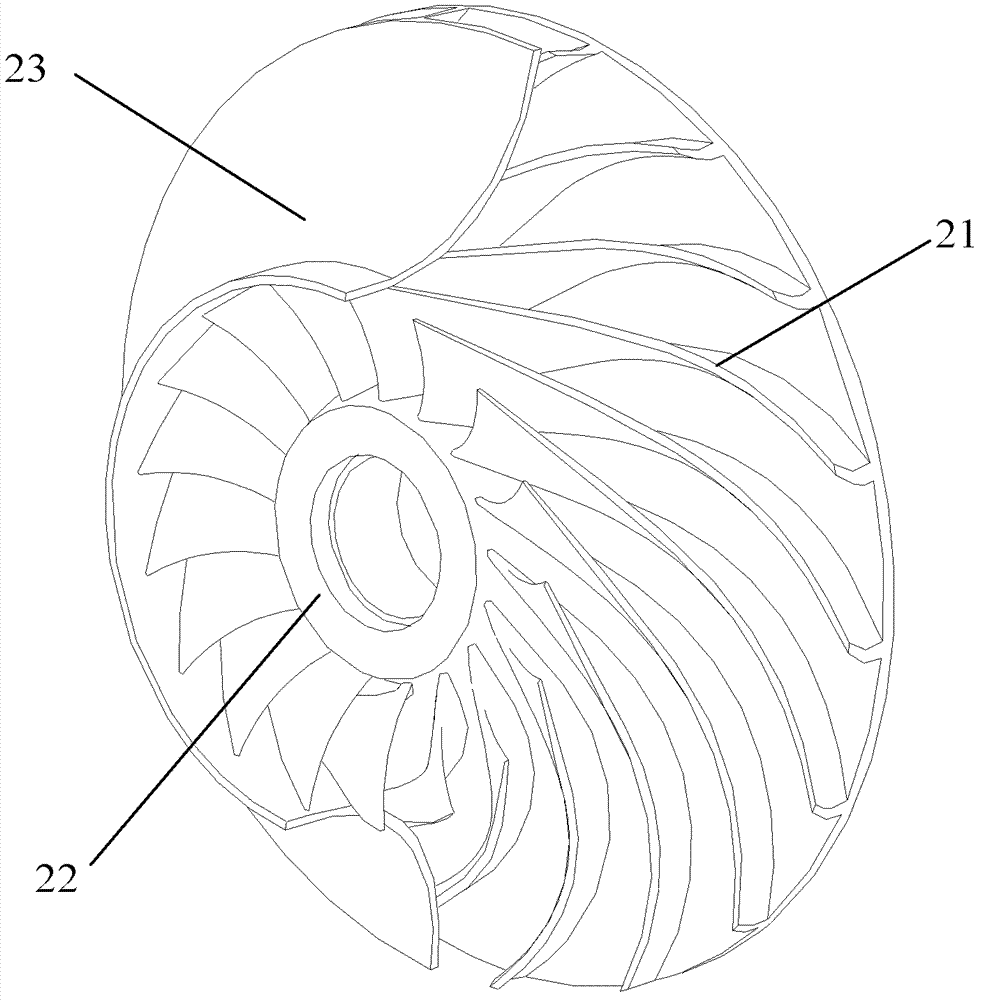
[0029] like figure 2 and image 3 As shown, the impeller provided by the present invention includes: a blade 21 and a hub 22 connected to one side of the blade 21, wherein the surface of the blade 21 is a blade curved surface with a control line 211 (such as Figure 4 As shown), the control lines 211 are combined to form the curved surface of the blade, wherein the control lines 211 are curved lines. Preferably, the present invention also includes a wheel cover 23 near the other side of the blade 21 .

[0030] When the present invention is in use, the structure of the hub 22 completes the function of transmitting torque from the rotating shaft to the impeller. Under the action of the torque...


PUM


Abstract

The invention provides an impeller and a centrifugal compressor comprising the same. The impeller comprises a hub and blades. Surfaces of the blades are blade curved surfaces, control lines on each blade are combined with one another to form the corresponding blade curved surface, and the control lines on at least one part of a surface region of each blade curved surface are curved lines. The impeller and the centrifugal compressor comprising the same have the advantages that the control lines of the blades of the impeller are changed into the curved lines instead of straight lines by the aid of a three-dimensional design of the impeller, so that middles of the blades of the centrifugal impeller have certain curvature, impact on an inlet of the impeller is reduced or eliminated, separation loss of the inlet of the impeller is reduced or eliminated, a fluid flowing structure inside the impeller is improved, the efficiency of the impeller is further enhanced, the range of a high-efficiency area is broadened, and surge flow is reduced.

Description

technical field [0001] The invention relates to the field of fluid machinery, in particular to an impeller and a centrifugal compressor including the impeller. Background technique [0002] As the core moving part in the centrifugal compressor, the impeller plays the role of doing work on the gas and making the gas gain energy, so as to achieve the purpose of compressing the gas. Therefore, the design of the impeller plays a decisive role in the performance of the centrifugal compressor. Since the performance of the impeller is mainly reflected in its aerodynamic performance, the design of the flow path inside the impeller is particularly critical. [0003] Among them, the aerodynamic performance of the impeller is mainly reflected in the following two aspects: [0004] 1. The effective power of the impeller to transfer the shaft power to the fluid, that is, the impeller efficiency. The energy loss in the impeller is composed of many factors, the most critical and difficul...

Claims


Application Information

Patent Timeline
Patent Type & Authority Patents(China)
IPC IPC(8): F04D29/28F04D29/30
Inventor 张治平钟瑞兴谢蓉蒋楠蒋彩云傅鹏闫秀兵
Owner GREE ELECTRIC APPLIANCES INC
Learn More